CIRCUTOR CVM-B Series User Manual
Page 104
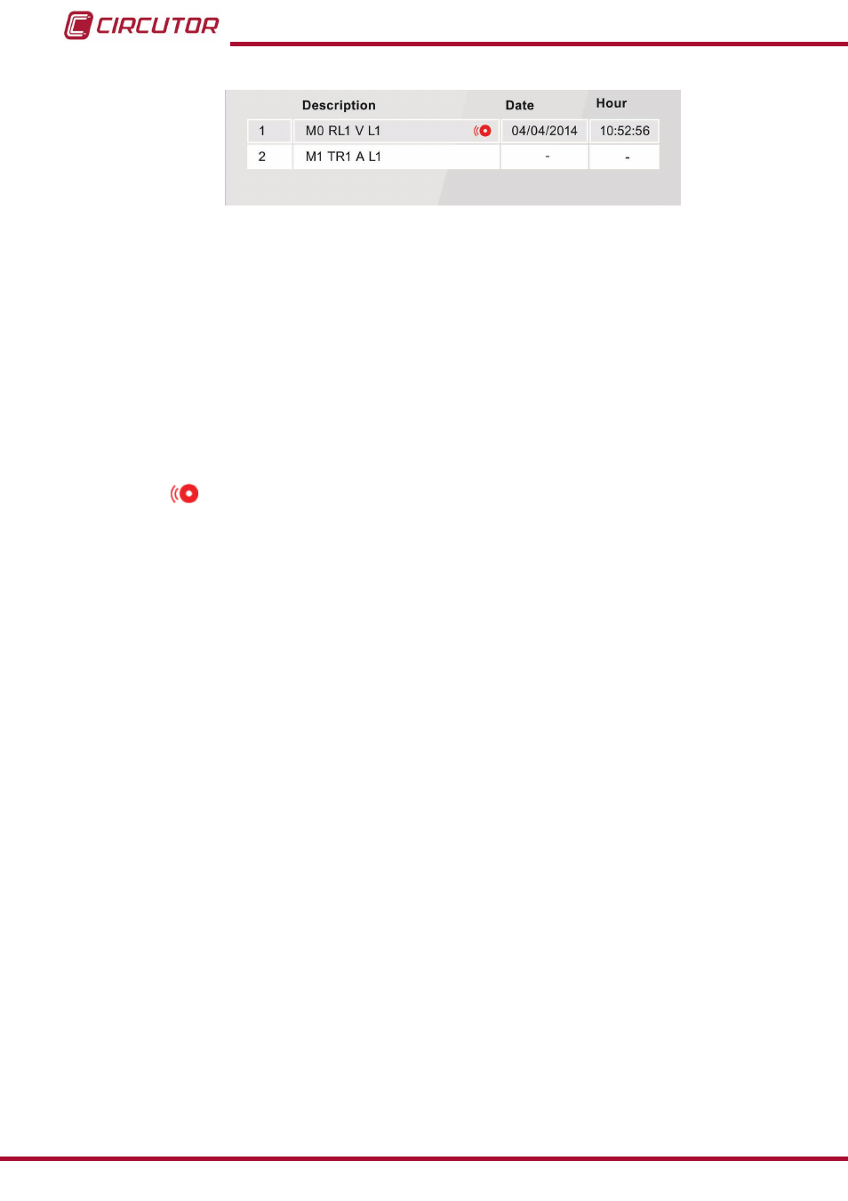
figure 88: Alarm menu description table�
The programmed alarms description table ,
figure 88
, is made up of 4 columns:
Cd� : Indicates the code of the variable that controls the programmed alarm,
Table 21
.
Description : Description of alarm that you have programmed.
Example: M0 RL1 V L1
M0,
Indicates that an alarm is integrated in the unit.
RL1,
Indicates that it is output 1 of the relay digital outputs.
V
L1,
The variable that controls the alarm is Phase-Neutral Voltage of phase 1.
The icon
indicates that the alarm has been activated.
Date : If the alarm has been activated, the date when this occurred will be displayed.
Time : If the alarm has been activated, the time when this occurred will be displayed.
104
CVM-B100 - CVM-B150
Instruction Manual