Connection diagram, Configuration, 7�5�3�- connection diagram – CIRCUTOR CVM-B Series User Manual
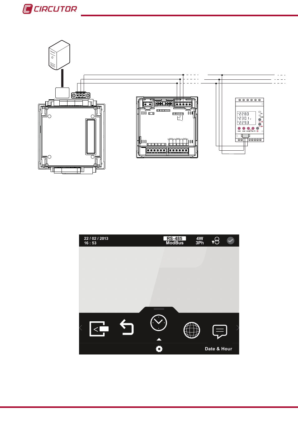
Page 260: The screen in, Is the home screen of the setup menu, Figure 25, Figure 180, Figure 179:modbus tcp (bridge) connection diagram, Figure 180: main screen of setup menu, Ethernet rs-485
Advertising

7�5�3�- CONNeCTION DIAgRAM
B(-)
A(+)
S
PC
Ethernet
RS-485
POWER SUPPLY
INPUTS
A
(+) B(-)
GND
RS485
S1
S2
S1
S2 S1
S2
L1
P1
P2
L2
L3
300V ~
Ph-N
Ph-Ph
520V ~
N
V
L3
L2
V
L1
V
P1
P2 P1
P2
I1 I2
OUTPUTS
Rc R2 R1
Tc T2 T1
S0- S0+ S0+
B(-)
A(+)
S
CVM B-1xx
+
M-CVM-AB-Modbus TCP (Bridge)
CVM C10
CVM MINI
figure 179:Modbus TCP (Bridge) connection diagram�
7�5�4�- CONfIgURATION
You can access the setup menu on the main screen,
figure 25
.
The screen in
is the home screen of the setup menu.
figure 180: Main screen of setup menu�
260
CVM-B100 - CVM-B150
Instruction Manual
Advertising