Typical application – Basler Electric BE1-11g User Manual
Page 150
138
9424200994 Rev N
Table 51. Operational Settings
Setting
Range
Increment
Unit of
Measure
Default
Mode
Disabled, Non-Voltage Control,
Voltage Control, or Both
n/a
n/a
Disabled
Directional Supervision
Angle
–90 to 0
0.1
degrees
–15
Diameter 1
0.1 to 100 (5A CTs)
0.5 to 500 (1A CTs)
0.1
ohms
1
Diameter 2
0.1 to 100 (5A CTs)
0.5 to 500 (1A CTs)
0.1
ohms
1.4
Offset 1 & 2
0 to 110 (5A CTs)
0 to 550 (1A CTs)
0.1
ohms
1.1
Time Delay 1 & 2
0 to 300,000
varies
milliseconds
0
Voltage Pickup 1 & 2
0 or 5 to 180
1
volts
0
Voltage Time Delay 1 & 2
0 to 300,000
varies
milliseconds
0
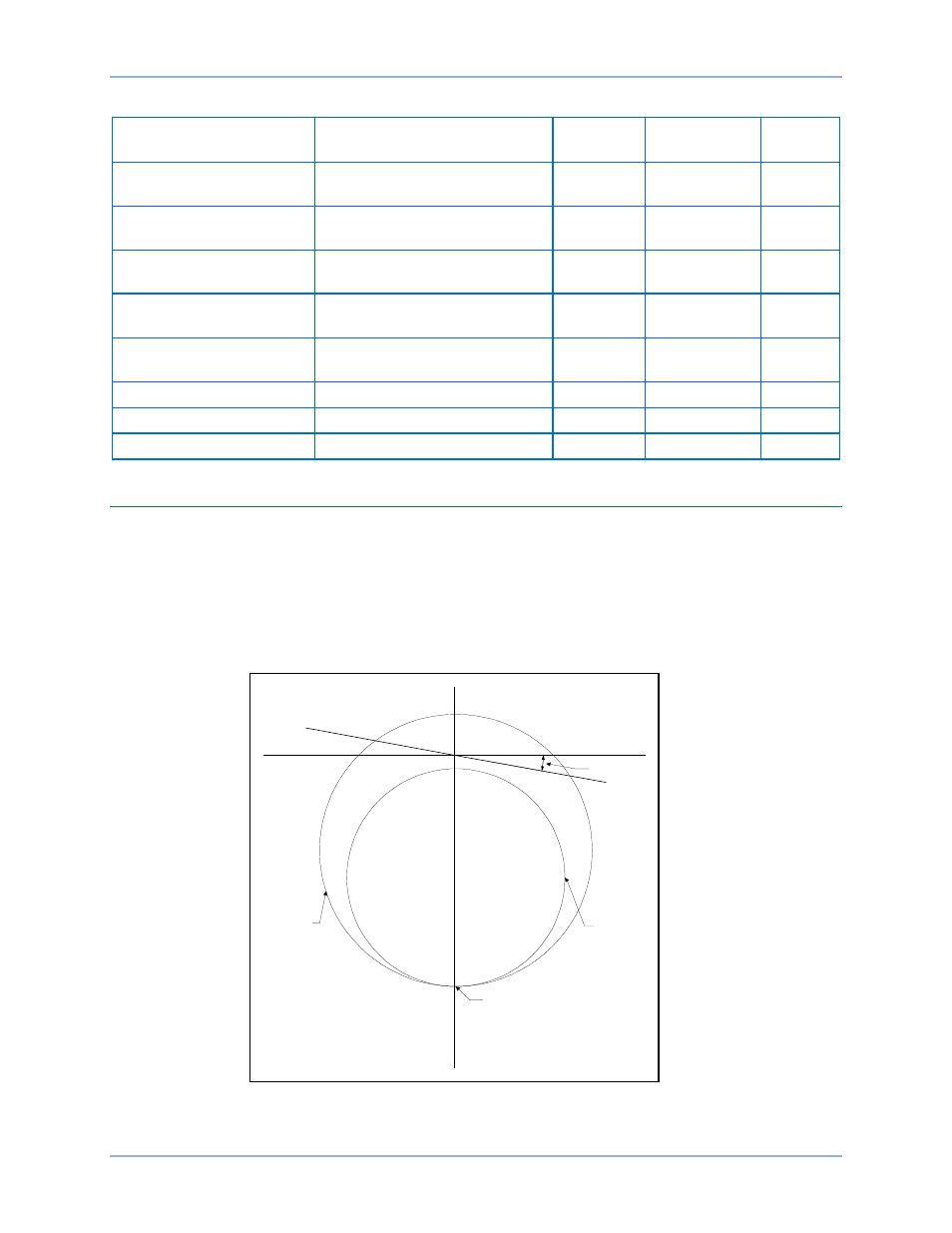
Typical Application
Settings and measurements are used to determine if the measured system impedance is within the
tripping criteria to indicate loss of excitation.
This consists of two mho circles with the lower edge offset from the R axis by an equal distance typically
set to 1.1
*Xd. The diameter of the smaller circle (Z1) is typically set so that the upper edge is located at
X’d/2 below the R axis. The larger circle (Z2) and the directional blocking are both set to coordinate with
the steady-state stability limit of the generator. The larger circle has a time delay to prevent nuisance
tripping. Refer to Figure 87.
Figure 87. Typical Application
X
Offset
Z1 Diameter
Z2 Diameter
R
Blinder Angle
P0037-02
01-16-06
Loss of Excitation - Impedance Based (40Z) Protection
BE1-11g