Retrieving contact-sensing input status, Contact outputs – Basler Electric BE1-11g User Manual
Page 49
9424200994 Rev N
37
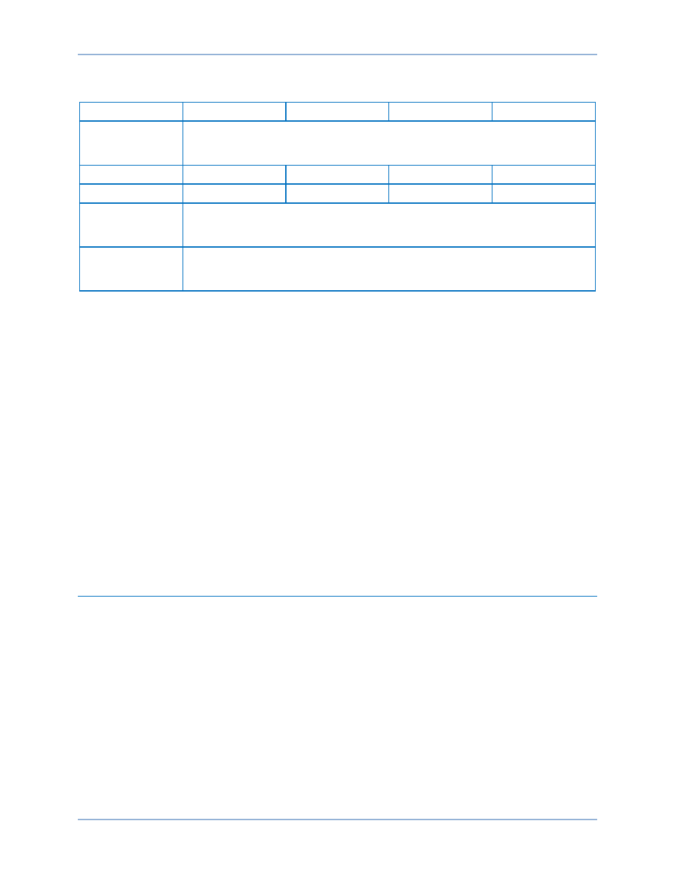
See Table 6 for a list of settings and their defaults.
Table 6. Contact Input Settings
Setting
Range
Increment
Unit
Default
Label
User programmable label for the input contact. Used by the reporting function to
give meaningful identification to the input contact. This label can be up to 64
characters long.
Recognition Time
4 to 255
1
*
milliseconds
4
Debounce Time
4 to 255
1
*
milliseconds
16
Energized State
User programmable label for the energized state of the contact. Used by the
reporting function to give meaningful identification to the state of the input contact.
This label can be up to 64 characters long.
De-Energized
State
User programmable label for the de-energized state of the contact. Used by the
reporting function to give meaningful identification to the state of the input contact.
This label can be up to 64 characters long.
* Since the input conditioning function is evaluated every quarter cycle, the setting is internally rounded to
the nearest multiple of 4.16 milliseconds (60 Hz systems) or 5 milliseconds (50 Hz systems).
If you are concerned about ac voltage being coupled into the contact sensing circuits, the recognition time
can be set higher than one-half of the power system cycle period. This will take advantage of the half-
wave rectification provided by the input circuitry.
If an ac wetting voltage is used, the recognition time can be set to less than one-half of the power system
cycle period and the debounce timer can be set to greater than one-half of the power system cycle period.
The extended debounce time will keep the input energized during the negative half-cycle. The default
settings of 4 and 16 milliseconds are compatible with ac wetting voltages.
Settings for contact inputs can also be entered through the front panel.
See the
chapter for an illustration of the programmable output terminals.
Contact output electrical ratings are listed in the
chapter.
Retrieving Contact-Sensing Input Status
Contact input status is determined through BESTCOMSPlus by using the Metering Explorer to open the
Status, Inputs tree branch. BESTCOMSPlus must be online with the BE1-11g to view contact input status.
Alternately, status can be determined through the front-panel display by navigating to Metering > Status >
Inputs.
Contact Outputs
A BE1-11g in a J type case has eight contact outputs (OUT1 through OUT8) and one failsafe, normally
open or closed (when de-energized) alarm contact output (OUTA). Five contact outputs (OUT1 through
OUT5) are provided in an H or P type case.
Each output is isolated and rated for tripping duty. OUT1 through OUT8 are Form A (normally open), and
OUTA is Form B (normally closed) or Form A (normally open).The style number determines the type of
alarm contact output. A trip coil monitoring circuit is hardwired across OUT1. See the
Trip Circuit Monitor
chapter for details.
Contact outputs OUT1 through OUT8 and OUTA are driven by BESTlogicPlus expressions for OUT1
through OUT8 and OUTA. The use of each contact output is completely programmable so you can assign
meaningful labels to each output and to the logic 0 and logic 1 states of each output. The
chapter has more information about programming output expressions in your programmable logic
schemes.
BE1-11g
Contact Inputs and Outputs