Comtech EF Data CST-5000 User Manual
Page 114
CST-5000 C-Band Satellite Terminal
Maintenance
Rev. 9
6–3
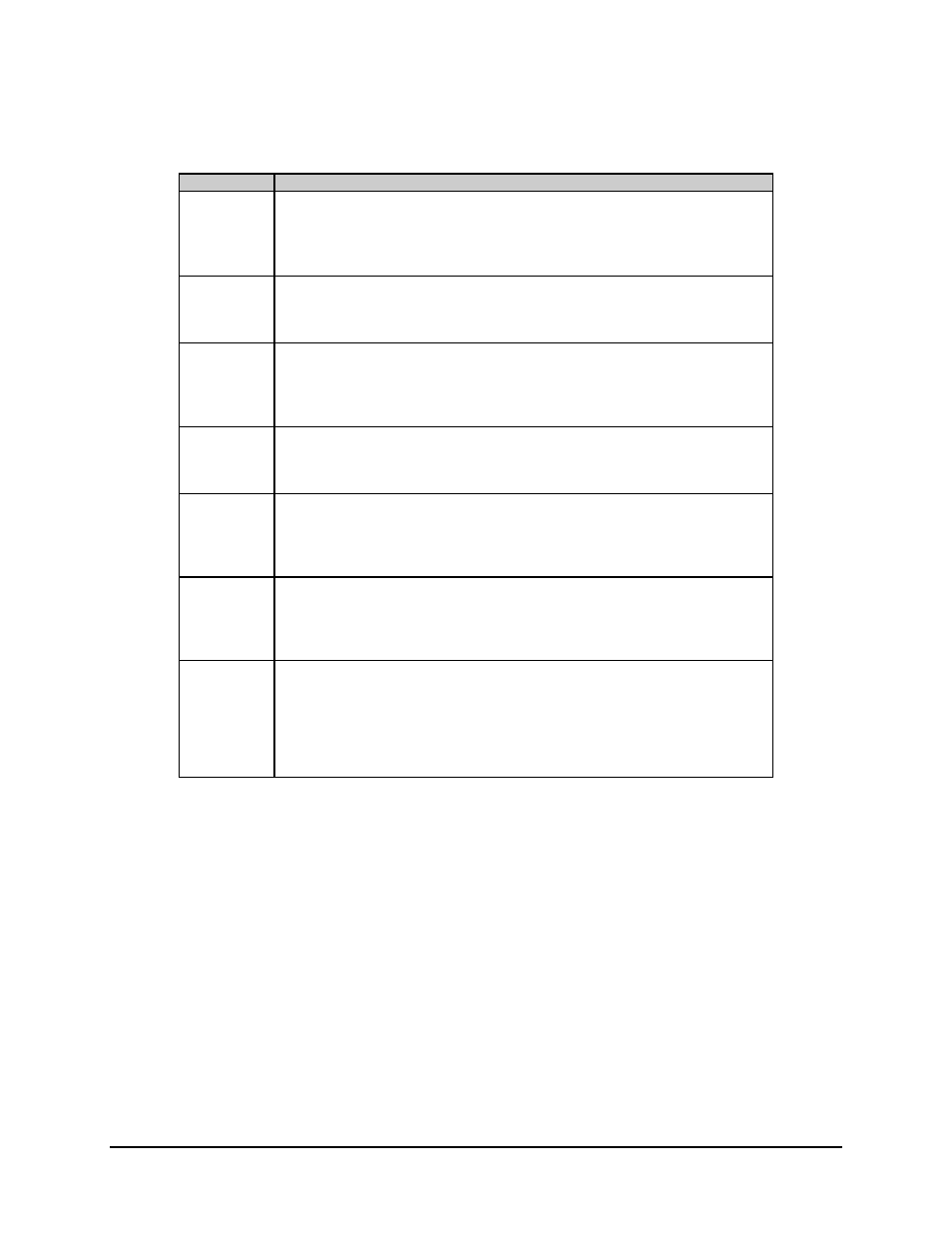
Table 6-3. Fault Isolation
Fault
Possible Problem and Action
+5 VOLT
+5V power supply fault.
Indicates the +5V power supply on the M&C board is at a high or a low voltage
condition. Allowable level variation is
± 5%. Check for a short on the +5V line, or
faulty connection at P3 on the M&C.
+12 VOLT
+12V supply fault.
Indicates the +12V supply is at a high or low voltage condition. Check for a short on the
+12V line, or faulty connections between any of the internal modules.
HPA
High Power Amplifier fault.
Check for a loose connector at P12 or that XFE has not been turned on, then replace the
HPA. The HPA is not intended to be opened in the field. Once the problem has been
isolated, the transmitter must be turned back on.
LNA
Low Noise Amplifier fault.
Check the RF cable to the LNA and that LFE is not on with no LNA attached. If
acceptable, replace the LNA.
U/C LOCK
Up converter lock fault.
Check for loose connections at P7, P8, and P4. Also, check all RF coaxial connectors on
the U/C synthesizer and U/C board before replacing modules. Once the problem has
been isolated, the transmitter must be turned back on.
U/C TUN
Up converter tuning fault.
Check for loose connections at P7, P8, and P4. Also, check all RF coaxial connectors on
the U/C synthesizer and U/C board before replacing the modules. Once the problem has
been corrected, the transmitter must be turned back on.
D/C TUN
Down converter tuning fault.
Check for loose connections at P10, P11, and P4. Also, check all RF coaxial connectors
on the D/C synthesizer and D/C board before replacing the modules. Once the problem
has been corrected, the transmitter must be turned back on.
Note: Not available in single synthesizer option.