1 redundant plate installation, 4 1:1 redundant plate installation – Comtech EF Data CST-5000 User Manual
Page 72
Redundant System Installation
CST-5000 C-Band Satellite Terminal
3–18
Rev. 9
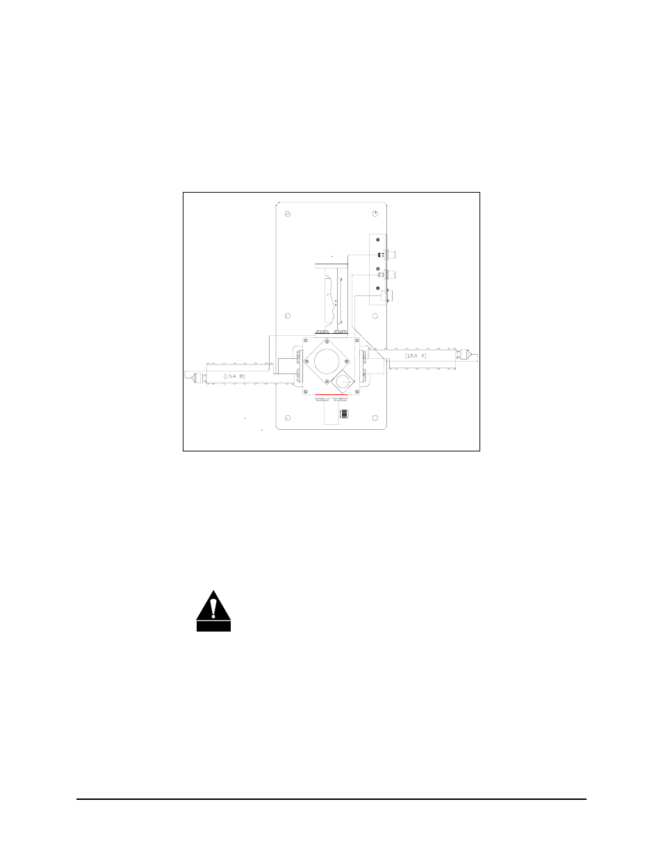
3.3.4 1:1 Redundant Plate Installation
The 1:1 redundant plate is shown below. Refer to Section 3.2.1 for included parts.
To install the 1:1 redundant plate:
1. Mount the 1:1 redundant plate to the antenna.
Note: The type of mounting is determined by the brand of antenna on which the
equipment will be installed.
2. Remove the plastic cover from the RF IN connector of the redundant plate.
CAUTION
After removing the protective cover, ensure that no foreign material
or moisture enters the 1:1 redundant plate’s waveguide.
3. Install the appropriate gasket on the RF IN connector of the redundant plate:
a. If the TR Filter_Plate/waveguide has a groove, and the antenna flange does
not, the thin gasket should be used.
b. If both the TR Filter_Plate/waveguide and the antenna flange have grooves,
the thick gasket should be used.