Rx/rf input (j4), Prime power (j5), 4 rx/rf input (j4) – Comtech EF Data CST-5000 User Manual
Page 51: 5 prime power (j5)
CST-5000 C-Band Satellite Terminal
Single Thread System Installation
Rev. 9
2–23
2.5.4 RX/RF Input (J4)
The RX/RF input is a type N connector that receives the signal from the LNA. The input
impedance is 50
Ω
.
The input frequency range is from 3.620 to 4.200 GHz.
The input signal level ranges between -50 and -25 dBm, depending on LNA and antenna
gain.
The input level should be set to give the required signal level at J3, the RX/IF Output
(refer to Section 2.5.3).
2.5.5 Prime Power (J5)
The AC power is supplied to the RFT by a 3-pin circular connector.
Normal input voltage is 95 to 230 VAC, 47 to 63 Hz.
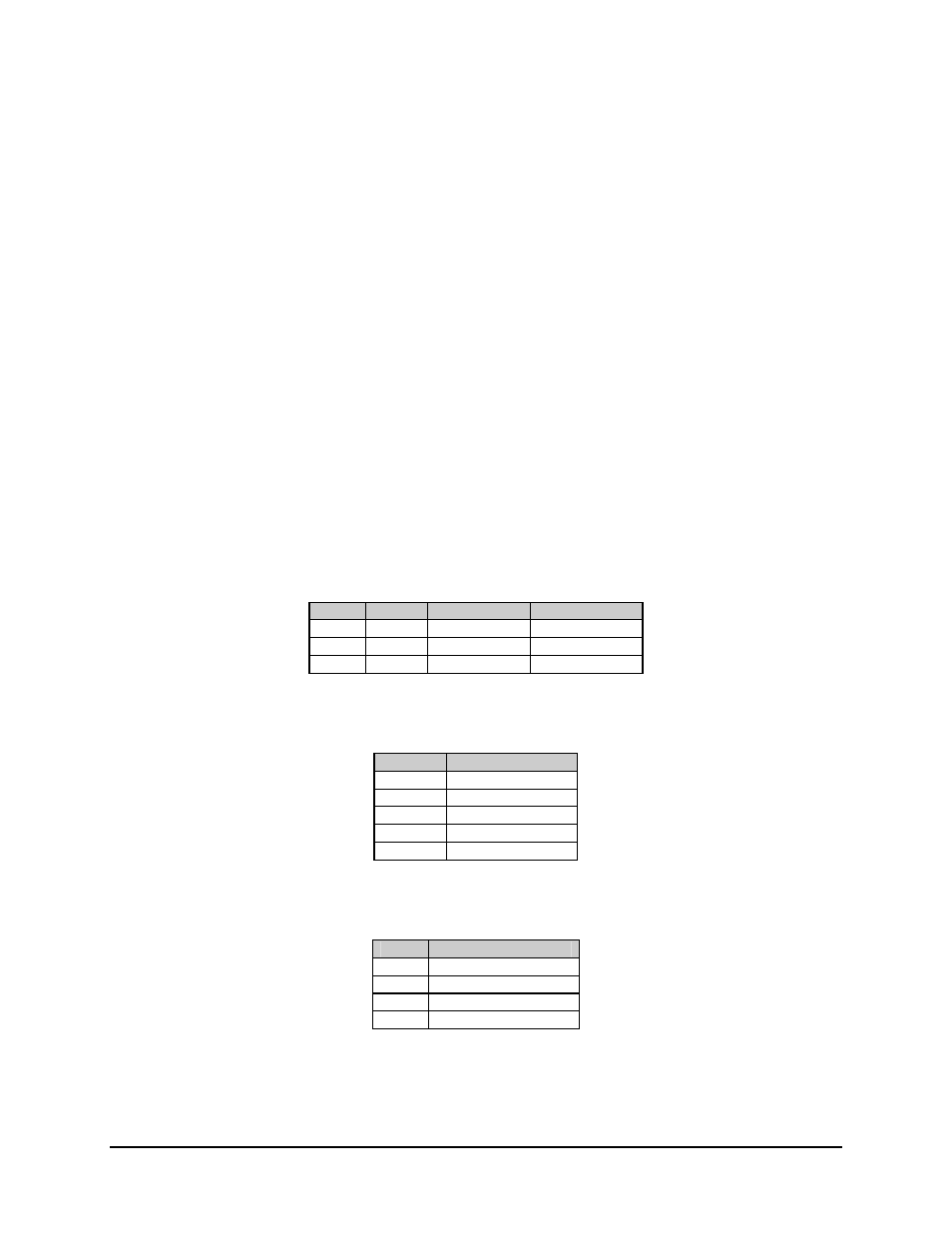
The AC pinout is as follows:
Pin #
Name
Function
Wire Color
A HI Line
Brown
B LO Neutral/Line Blue
C GND Ground Green/Yellow
Maximum power consumption depends on the power amplifier used in the RFT. The
following is a list of maximum power consumption at each configuration:
SSPA
Maximum Power
+8 dBm
90W
5W 140W
10W 210W
20W 340W
40W 600W
A circular 4-pin power connector is used for the 48 VDC option. The pinout is as
follows:
Pin #
Function
A +
INPUT
B CHASSIS
GROUND
C -
INPUT
D -
N/C