M&c board connector pinouts, 2 remote relay control, j2 db15-female – Comtech EF Data CST-5000 User Manual
Page 95
Theory of Operation
CST-5000 C-Band Satellite Terminal
5–6
Rev. 9
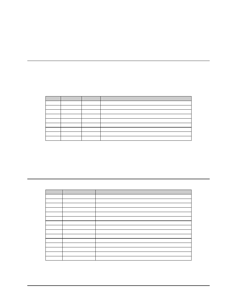
5.1.5 M&C Board Connector Pinouts
5.1.5.1 EIA-232/485 Remote Control (J1)
The remote interface is provided on a 9-pin female D connector. Screw locks are
provided for mechanical security of the mating connector. The remote connector is a Data
Circuit Terminating Equipment (DCE) interface. Refer to the following listing for pin
assignments:
Pin #
EIA-232
EIA-485
Description
1 GND
GND Ground
2 TD/TX
Transmit
Data
3 RD/RX
Receive
Data
4
+RX/TX
Plus Transmit or Receive
5
GND
-RX/TX
Negative Transmit or Receive
6
DSR
Data Set Ready
7
RTS
Ready to Send
8
CTS
+RX/TX
Clear to Send (EIA-485 - Plus Transmit or Receive)
9
-RX/TX
Negative Transmit or Receive Data
Notes:
1. Clear to Send (CTS) is tied to Ready to Send (RTS) in EIA-232 mode.
2. The pinout for Data Terminal Equipment (DTE) interface is provided for
EIA-232.
5.1.5.2 Remote Relay Control, J2 DB15-Female
Pin #
Name
Description
1
EXT PWR
Output voltage, 11V, 1A
9
LNA_PWR
10V to LNA
2
NO A
Summary fault relay A
10
COM A
Normal operation, common connects to NO
3
NC A
Fault mode, common connects to NC
11
NO B
Summary fault relay B
4
COM B
Normal operation, common connects to NO
12
NC B
Fault mode, common connects to NC
5 SPARE
13 SPARE
6
ALOG TST
Analog voltage output, TBD
14
LNA_PWR_RTN
Ground Return for LNA
7
EXT INPUT2
Input, logic 0 (normal) or 5V (fault)
15
EXT TWT FLT
Input, logic 0 or 5V, used for TWT.FLT
8 GND
Ground