Tx/if input (j1), Tx/rf output (j2), Rx/if output (j3) – Comtech EF Data CST-5000 User Manual
Page 50: 1 tx/if input (j1), 2 tx/rf output (j2), 3 rx/if output (j3)
Single Thread System Installation
CST-5000 C-Band Satellite Terminal
2–22
Rev. 9
2.5.1 TX/IF Input (J1)
The TX/IF input is a TNC connector that receives the signal from the indoor unit. The
input impedance is 50
Ω
, and the frequency is 70 MHz
±
18 MHz (optional 140 MHz
±
36 MHz).
The typical power level is from -43 to -19 dBm, depending on the configuration and
application.
2.5.2 TX/RF Output (J2)
The TX/RF output is a type N connector that sends the signal to the antenna. The output
impedance is 50
Ω
. The output frequency range is from 5.845 to 6.425 GHz. The output
power level is dependent on the power amplifier ordered with the system.
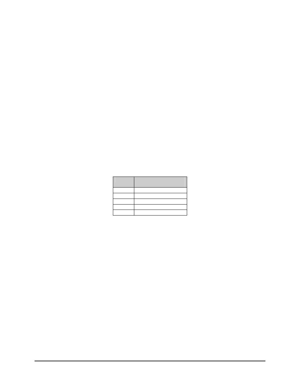
Table 2-2 lists the maximum output power at the 1 dB compression point for each SSPA
available:
Table 2-2. SSPA Maximum Output Power
SSPA
System Power at 1 dB
Compression Point
None +8
dBm
5W +37
dBm
10W +40
dBm
20W +43
dBm
40W +46
dBm
2.5.3 RX/IF Output (J3)
The RX/IF output is a TNC connector that sends the received signal to the indoor unit.
The output impedance is 50
Ω
, and the frequency is 70 MHz
±
18 MHz (optional
140 MHz
±
36 MHz).
The 1 dB output compression point is +15 dBm.
Maximum output power operation is +9 dBm (-6 dB from 1 dB compression) to -
50 dBm, depending on system gain requirements.
The down converter has 26 to 47 dB of gain, and is adjustable by the customer from 0 to
21 dB of attenuation.
The typical system gain includes a 50 dB LNA, making the total system gain 76 to 97 dB.
Note: A 60 dB LNA is used only when extremely long cables are used from the LNA to
the down converter.