Connecting the centum series, Connecting the centum series -22, Figur e3-1 – Verilink AS100 (896-502379-001) Product Manual User Manual
Page 47: Rear panel of access system 100 (v.35 version) -22, Figur e3-2, Rear panel of access system 150 (v.35 version) -22
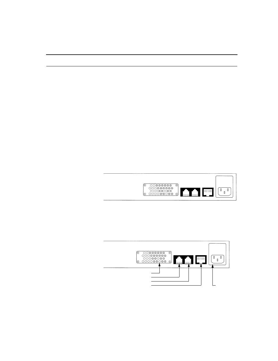
Connecting the Centum Series
Access System Centum Series User Manual
3-23
Connecting the Centum Series
After all units have been configured and self-tested, they should be
connected to the network via the 8-pin modular jack (RJ-48
configuration).
The User DTEs and the DSX-1 should also be connected at this time.
The V.35 DTE connects to the DSU via female M-series, 34-pin
connectors.
RS-530 DTEs connect to the DSUs via female DB-25 connectors.
RS-449 (37-pin) DTEs connect to the DSUs via mechanical adapters and
female DB-25 connectors. The DSX-1 port is an 8-pin modular jack
(RJ-48 configuration).
All cable specifications are given in Appe ndixB, Standard Cabling for
User Ports.
Figure 3-1
Rear Panel of Access System 100 (V.35 version)
Figure 3-2
Rear Panel of Access System 150 (V.35 version)
PRN AUX
N.I.
PORT #1
V.35
PRN AUX
N.I.
PORT #1
V.35
V.35 DTE
ter Support and NMS Access
Terminal Access
nection (RJ-48 Configuration
Power cord
M-series 34-pin Receptacle
6-pin
Modular Jacks
8-pin
Modular
Jack
connection
-1 Port (RJ-48 Configuration)