Modular adapters, Rear panel views, Modular adapters -4 – Verilink AS100 (896-502379-001) Product Manual User Manual
Page 78: Rear panel views -4, Figur e6-1, Pin modular adapter pin assignments -4, Figur e6-2, Rear panel of access system 100 (v.35 version) -4
6-4
Access System Centum Series User Manual
Modular Adapters
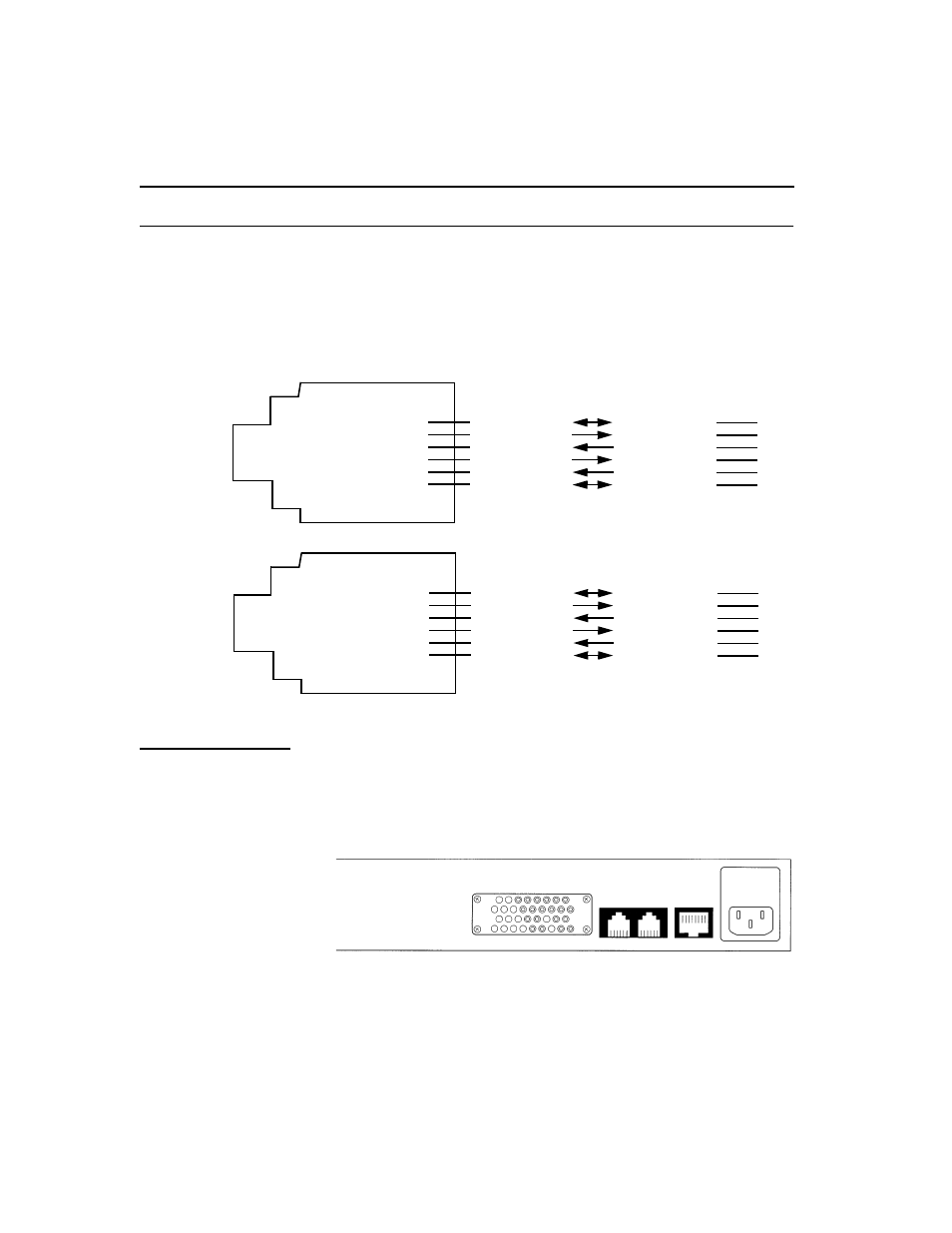
If Verilink cables will not be used, the adapters shown below should be
used with straight-through male/male 6-wire modular cables. See
previous page for a description of the available Verilink cables.
Figure 6-1
6-Pin Modular Adapter Pin Assignment
Rear panel views
The three following figures show the rear panel views of the AS100,
AS150, and AS200, respectively. As an example, the AS150 rear panel is
labeled in detail.
Figure 6-2
Rear Panel of Access System 100 (V.35 version)
1
2
3
4
5
6
6-pin
Modular
Jack
(Female)
Signal Ground
Carrier Detect
Request to Send
Receive Data
Transmit Data
Power Ground
Signal Ground
Carrier Detect
Request to Send
Receive Data
Transmit Data
Power Ground
7
8
4
3
2
1
Direct
Connection
1
2
3
4
5
6
6-pin
Modular
Jack
(Female)
Signal Ground
Carrier Detect
Request to Send
Receive Data
Transmit Data
Power Ground
Signal Ground
Request to Send
Carrier Detect
Transmit Data
Receive Data
Power Ground
7
4
8
2
3
1
Modem
Connection
D
B
-25 Pins
To
/F
ro
m
Mo
d
e
m
D
B
-25 Pins
To
/F
ro
m
T
e
rm
ina
l
or Pri
nt
er
PRN AUX
N.I.
PORT #1
V.35