Supervisory configuration menu, Supervisory configuration menu -17 – Verilink FrameStart FSM (34-00299.E) Product Manual User Manual
Page 135
F r o n t P a n e l L C D I n t e r f a c e
5-17
Number of Channels
This display-only field shows the number of channels to be passed through to
the DTE.
Values: 0 through 24
Default: 24
V.54
Selecting “Enable” allows the unit to respond to in-band V.54 loop codes. If
you select “Disable,” the unit ignores these codes.
Values: Disable, Enable
Default: Disable
LL
The Local Loopback parameter can be set to “Enable” or “Disable.” Selecting
“Enable” allows the unit to go into Local Loop when the LL pin on the Serial
port goes high. The unit exits the loop when the LL pin goes low. If you
select “Disable,” the unit ignores the LL pin on the Serial port.
Values: Disable, Enable
Default: Disable
For more information on pin assignments, refer to Serial Interface Pin
Assignments, DTE Mode (Packet Use Only) on page A-6 and Serial Interface
Pin Assignments, DCE Mode on page A-7.
DTR Control
This lets you set the Data Terminal Ready (DTR) alarm control parameters.
Choices for DTR Alarm Control are “Enable” and “Disable.” Setting DTR
Alarm Control to “Enable” allows the unit to go into alarm on a loss of DTR.
Values: Disable, Enable
Default: Disable
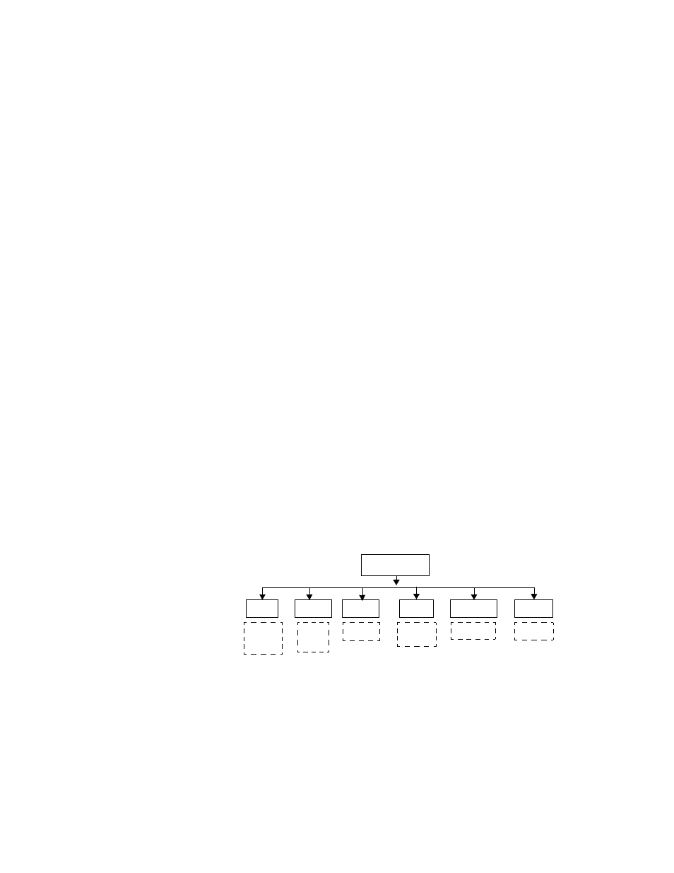
Supervisory Configuration Menu
Use the SUPV menu to set up parameter values for the Supervisory port as
shown in Figure 5.14 and defined in the paragraphs below.
Figure 5.14
Supervisory Configuration Menu
Speed
Changes the Supervisory port speed (in bits per second).
Values: 1200, 2400, 4800, 9600, 19200, 38400, 57600, 115200
Default: 19200
Ch Size
Selects the number of bits required to make up one asynchronous character.
Values: Five, Six, Seven, Eight
Default: Eight
Supv
Config
Speed
Parity
Stop Bits
1200, 2400,
4800,9600,
19200, 38400,
57600, 115200
None
Odd
Even
1
2
DTR Alarm
Dis
En
Diag Msgs
Dis
En
Five
Six
Seven
Eight
Ch Size