Power connection, Power connection -7 – Verilink FrameStart FSM (34-00299.E) Product Manual User Manual
Page 19
A b o u t t h e F r a m e S t a r t F S M
1-7
Calculations are based on a cable temperature of 70
°
F, 0.083
µ
F/ mile
capacitance, a 27-dB loss, and a 100-
Ω
, non-loaded, twisted-pair cable.
CAUTION:
In accordance with FCC Rules, Part 68.218(b), you must notify the
telephone company prior to disconnecting this product.
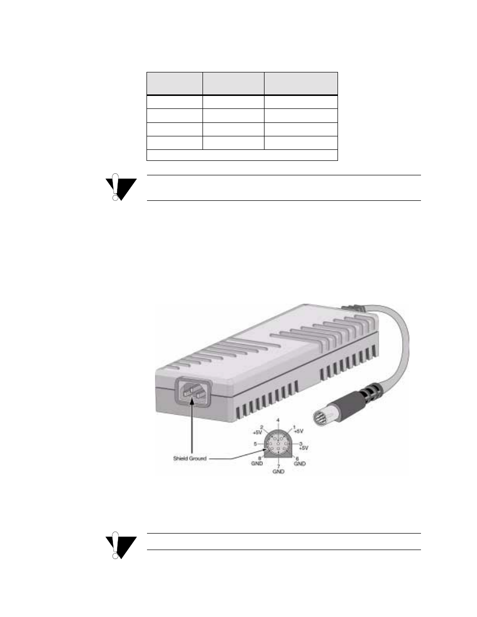
Power Connection
The
POWER
port is an eight-pin circular mini-DIN connector that connects
the autoranging 100–240 VAC external power supply to the unit. The FSM is
intended to be used with a UL Listed/CSA Certified Class 2 power supply
with a minimum output rating of 4.0 A at +5 VDC. The unit has no power
switch.
Figure 1.3
FSM Power Supply Unit
When power is applied to the unit, the front panel indicators flash for
approximately 10 to 15 seconds as the unit initializes. The green
POWER
LED on the front panel will remain illuminated as long as the unit receives
power. This LED turns amber when the unit is in test mode.
CAUTION:
Always plug the external power supply into a grounded power outlet.
Cable Type
Loss per 1000 ft
(dB)
Max Cable Length
(ft)
26-gauge PIC
6.8
4,400
24-gauge PIC
5.4
5,500
22-gauge PIC
4.2
7,100
19-gauge PIC
3.0
10,000
(PIC - Plastic Insulated Cable)