Current pin status, Dtr alarm control and status table, Services screen – Verilink FrameStart FSM (34-00299.E) Product Manual User Manual
Page 40: Services screen -16
3-16
F r a m e S t a r t F S M
Character Size
Selects the number of bits required to make up one asynchronous character.
Values: Five, Six, Seven, Eight
Default: Eight
Diagnostic Messages
Enables the Supervisory port to send out diagnostic messages upon power-up.
Values: Enable, Disable
Default: Enable
Parity
Sets the parity bit if the port is asynchronous.
Values: None, Odd, Even
Default: None
Stop Bit
Selects the number of bits required to end the character.
Values: 1, 2
Default: 1
Current Pin Status
The Current Pin Status, which shows the state of the RS-232 pins, is also
displayed on the Supervisory interface screen.
DTR Alarm Control and Status Table
In addition to the configurable fields, the Supervisory screen displays a table
that lets you set the Data Terminal Ready (DTR) Alarm Control parameters
and view the current DTR Alarm Status.
Choices for DTR Alarm Control are “Enable” and “Disable”; the default
setting is “Disable.” Setting DTR Alarm Control to “Enable” allows the unit
to go into alarm on a loss of DTR, which occurs when the Serial port detects
that the DTR signal is low. The DTR Status field indicates the current state of
the DTR alarm.
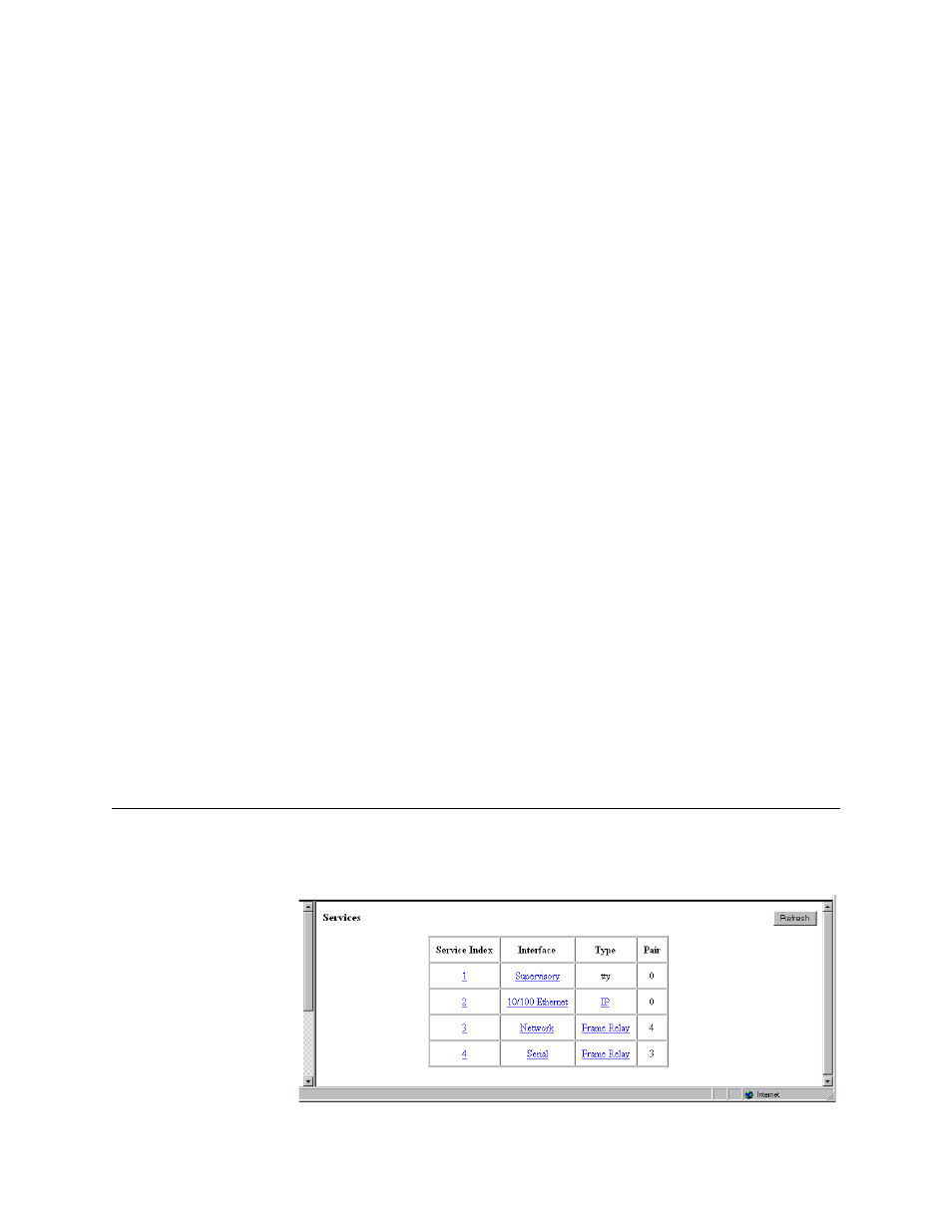
Services Screen
The Services screen (Figure 3.12) displays the unit’s defined services and the
Interface, Type, and Pair parameters for each service.
Figure 3.12
Services Screen