Verilink QUAD/IMUX (880-502392-001) Product Manual User Manual
Page 20
Quick Set-Up
2-2
Verilink QUAD/IMUX User Manual
NOTE: When more than one QUAD/IMUX is installed in the same
shelf all QUAD/IMUX installations in that shelf must use the
same timing source. Each QUAD/IMUX must have the
Receive
Receive
Receive
Receive
clock from shelf
clock from shelf
clock from shelf
clock from shelf option set to Yes
Yes
Yes
Yes. Each shelf may have only
one active timing source.
•
The IMUX 2160 in slot 4 uses 4 T1 circuits with a V.35 rear
interface module (DIM 2635). The IMUX 2160 in slot 9 uses 8
T1 circuits with a HSSI rear interface module (DIM 2660).
NOTE: Since the V.35, RS-449 and EIA 530 electrical interfaces only
provide reliable operation at rates up to 6 Mbit/s, any
QUAD/IMUX installation which uses more than 4 T1 circuits
or more than 3 E1 circuits requires the use of a HSSI rear
connector module (DIM 2660) for the IMUX 2160. HSSI is
designed to provide reliable operation at up to 52 Mbit/s.
•
The DTE (Data Terminal Equipment) to be connected at each
site consists of TCP/IP routers. At the central site two different
WAN ports of the same router will be connected to the two
QUAD/IMUX installations.
•
All of the T1 circuits use ESF framing and B8ZS line coding.
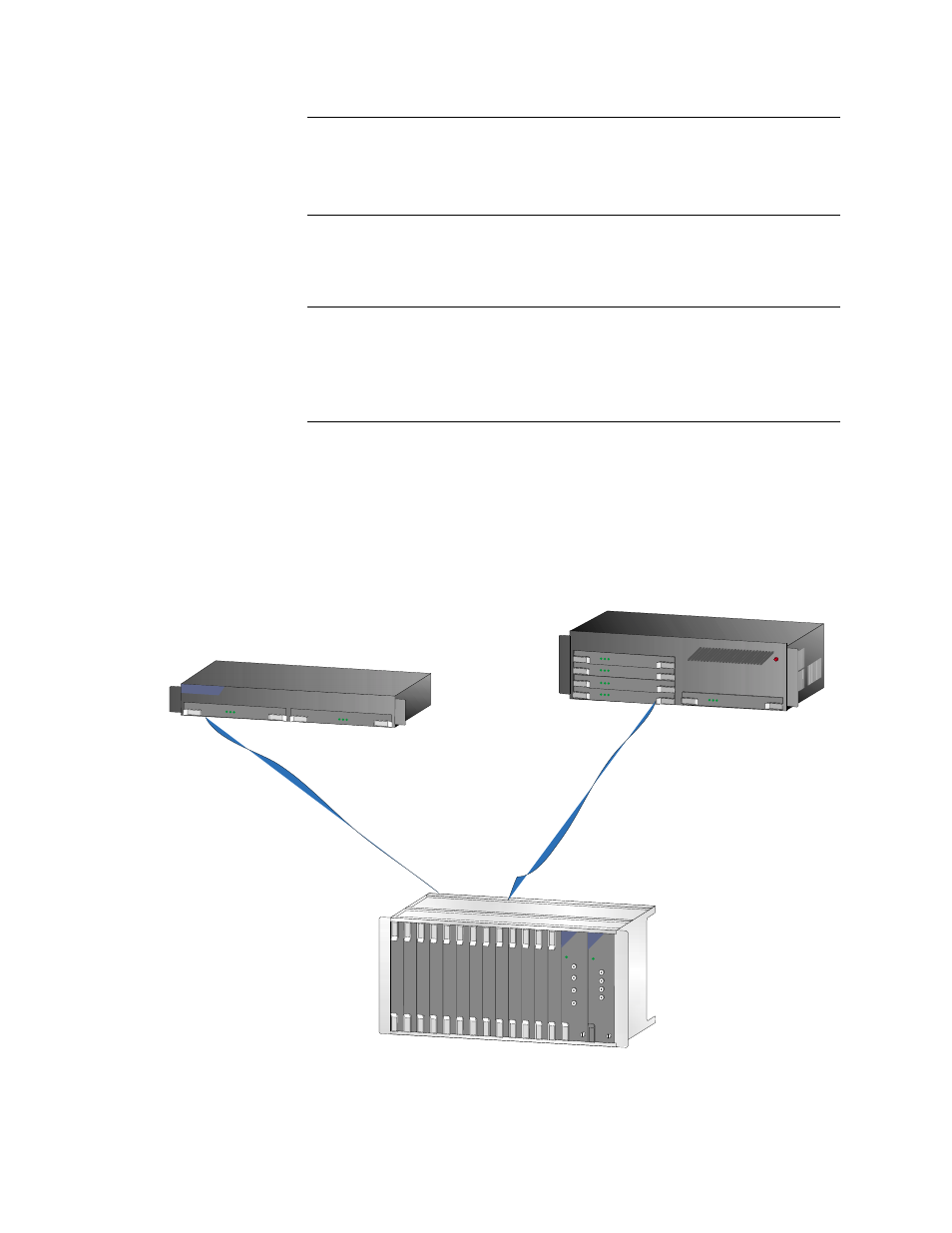
Figure 2-1 Example Configuration
ACCESS SYSTEM 2000
Remote Site w/ 8 T1s
Remote Site w/ 4 T1s
Central Site w/ two QUAD/IMUX installations