Setting up the display station, Figure 2-3. 1486a/g/p receptacle connectors, Power, connector – Visara 1486 User Manual
Page 19: Printer, connector, Twinax, connector, Connectors, Receptacle connectors, Setting up, Connector, Power cable
701334-002
2-7
Customer Installation
Setting Up the Display Station
1) If you are installing more than one 1486A/G/P and they will be daisy chained by
way of the twinax cable, begin with the 1486A/G/P that will be connected closest to
the System/3X, AS/400, or remote control unit.
2) Place the Display/Logic element within connecting distance of an appropriate AC
power outlet.
3) Place the keyboard in front of the Display/Logic element. Pull out the feet underneath
the keyboard to adjust it to a higher setting, if desired. Insert the keyboard plug into
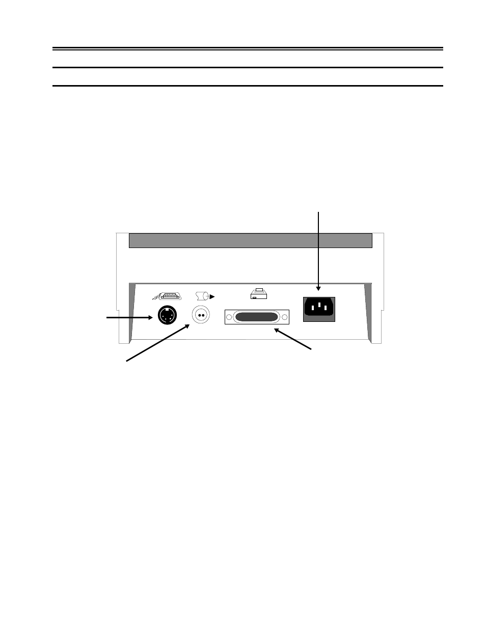
the keyboard connector on the back of the Display/Logic element (Figure 2-3, below).
Figure 2-3. 1486A/G/P Receptacle Connectors
4) Ensure that a key is inserted into the security keylock located on the right side of the
Display/Logic element (Figure 3-1 on Page 3-1).
5) Attach the printer cable (provided with the printer) to the connector on the back of
the Display/Logic element as displayed in Figure 2-3, above.
6) Make sure that the Power-On/Off switch is set to Off (see Figure 3-1 on Page 3-1).
7) Plug the power cord into the power receptacle on the back of the Display/Logic
element (see Figure 2-3, above).
Power
Connector
Keyboard
Connector
Twinax
Connector
Printer
Connector