2 wiring power inputs, Wiring power inputs – Westermo PMI-110-F2G User Manual
Page 16
2.2
Wiring Power Inputs
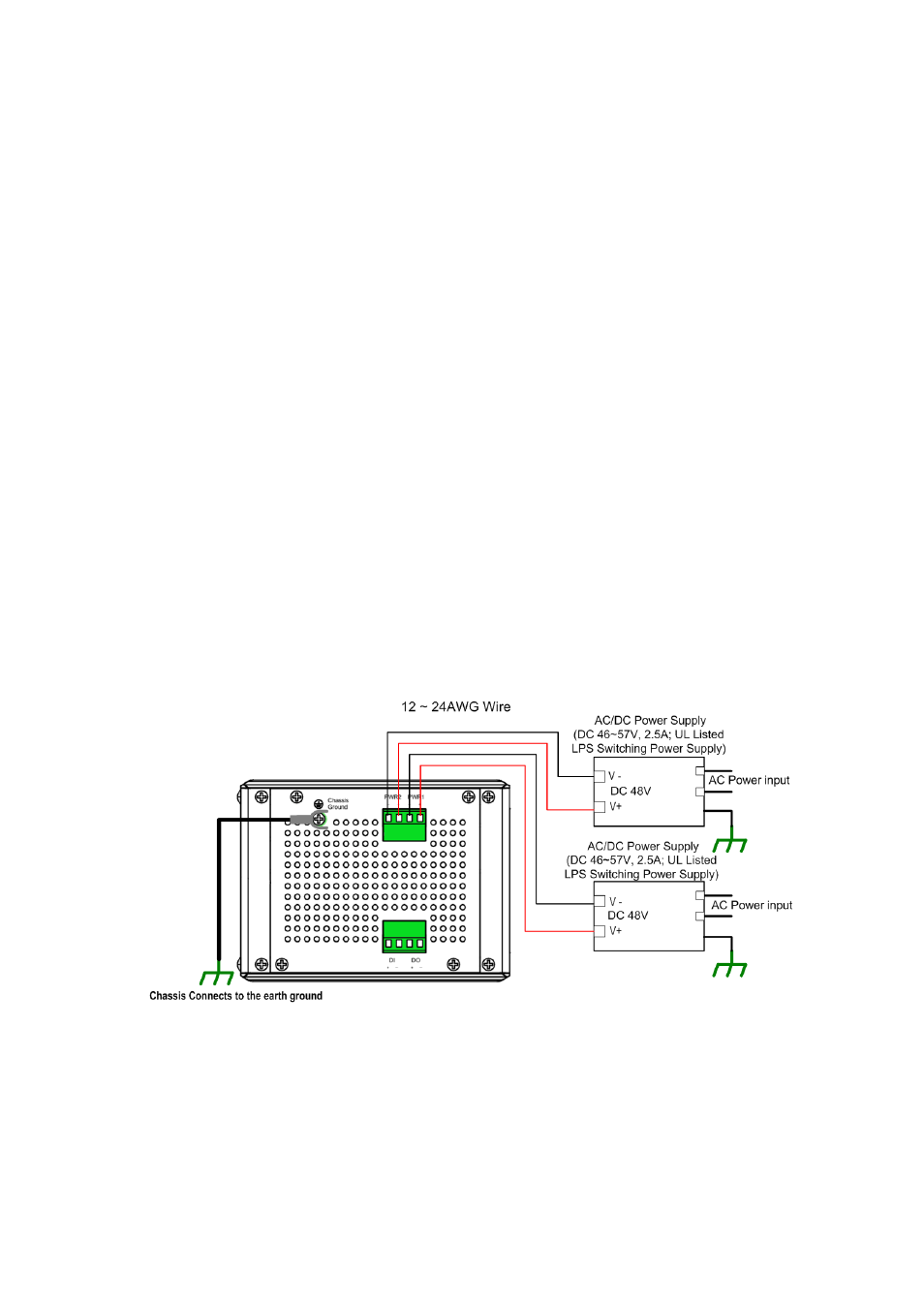
The Power input port is located at the bottom side, and provides 2 power input
connections in one 4‐pin removable terminal block. The power port support polarity
reverse protection; the Switch won’t start if wrong polarity applied. The wiring
architecture please refers to below figure.
Wiring the Power Inputs
1.
Insert the positive and negative wires into the V+ and V‐ contact on the terminal
block connector.
2.
Tighten the wire‐clamp screws to prevent the power wires from being loosened.
3.
Connect the power wires to suitable AC/DC Switching type power supply. The
PMI‐110‐F2G provides Power over Ethernet function and is compliant with
IEEE802.3af/ IEEE802.3at standards; therefore, the input DC voltage should be in
the range of DC 46V to DC 57V.
For the safety issue, turn off AC power input source before connecting the AC/DC
Power supply module and the terminal block connectors. Besides, don’t turn‐on the
source of AC/DC power module and make sure all connections were well done then
power on the AC source to powering the Switch device. Otherwise, your screwdriver
blade may inadvertently short your terminal connections to the grounded enclosure
and cause damage.
Notes: Use the UL Listed LPS Power supply with output Rating 46~57V Vdc, minimum
2.5A currents. Here, we recommended using DC 48V as the operating voltage. It is
recommended to use 48vdc power supply.
12