Westermo PMI-110-F2G User Manual
Page 73
4.5.4 MSTP (Multiple Spanning Tree Protocol) Configuration
MSTP is the abbreviation of Multiple Spanning Tree Protocol. This protocol is a
direct extension of RSTP. It can provide an independent spanning tree for
different VLANs. It simplifies network management, provides for even faster
convergence than RSTP by limiting the size of each region, and prevents VLAN
members from being segmented from the rest of the group (as sometimes occurs
with IEEE 802.1D STP).
While using MSTP, there are some new concepts of network architecture. A
switch may belong to different group, acts as root or designate switch, generate
BPDU for the network to maintain the forwarding table of the spanning tree.
With MSTP, it can also provide multiple forwarding paths and enable load
balancing. Understand the architecture allows you to maintain the correct
spanning tree and operate effectively.
One VLAN can be mapped to a Multiple Spanning Tree Instance (MSTI). The
maximum Instance of PMI Managed Switch support is 16, range from 0‐15. The
MSTP builds a separate Multiple Spanning Tree (MST) for each instance to
maintain connectivity among each of the assigned VLAN groups. An Internal
Spanning Tree (IST) is used to connect all the MSTP switches within an MST
region. An MST Region may contain multiple MSTP Instances.
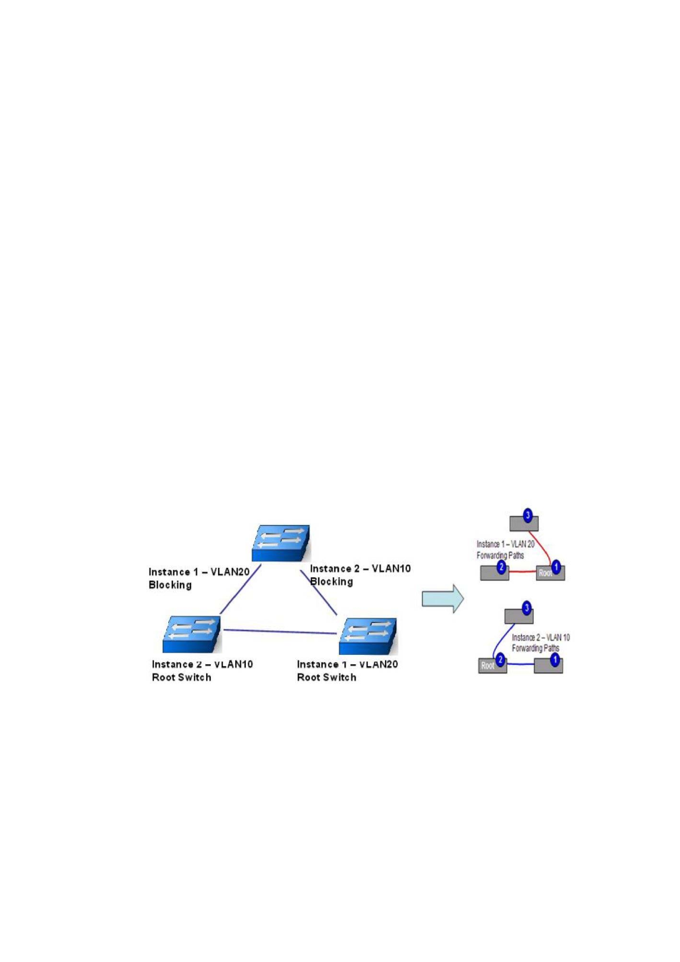
The figure shows there are 2 VLANs/MSTP Instances and each instance has its
Root and forwarding paths.
A Common Spanning Tree (CST) interconnects all adjuacent MST regions and acts
as a virtual bridge node for communications with STP or RSTP nodes in the global
network. MSTP connects all bridges and LAN segments with a single Common
and Internal Spanning Tree (CIST). The CIST is formed as a result of the running
spanning tree algorithm between switches that support the STP, RSTP, MSTP
protocols.
69