7 din rail mounting installation, Din rail mounting installation – Westermo PMI-110-F2G User Manual
Page 21
2.7
DIN Rail mounting Installation
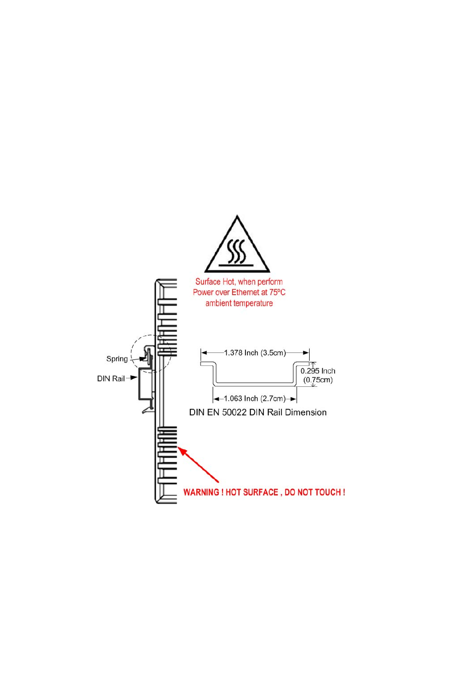
The DIN‐Rail clip is already screwed tight on the rear side of PMI Switch when shipping. If
the DIN‐Rail clip is not screwed on the rear side panel, please contact your distributor to
get the DIN rail clip set. The DIN rail clip supports EN50022 standard. The diagram
following includes the dimension of EN50022 DIN rail for your reference.
The Switch should install and used at Restriced Acess Location area, like as the control
room or control cabinet. Besides, the device’s surface temperature may caused damage
while the Power over Ethernet function is enabled and under working, at the ambient
temperature 70°C . Therefore, the device should install at the restriced location, like as
Control cabinet to prevent any damage.
Follow the steps below to mount PMI Managed Switch to the DIN‐Rail track:
1.
First, insert the DIN‐Rail track upper side into the upper end of DIN‐Rail clip.
2. Lightly push the bottom of DIN‐Rail clip into the track.
3. Check if DIN‐Rail clip is tightly attached to the EN50022 Rail track.
4. To remove PMI Switch from the track, reverse the steps above.
17