Grass Valley PDR v.2.2 User Manual
Page 95
Input and Output Mapping
Profile Family
77
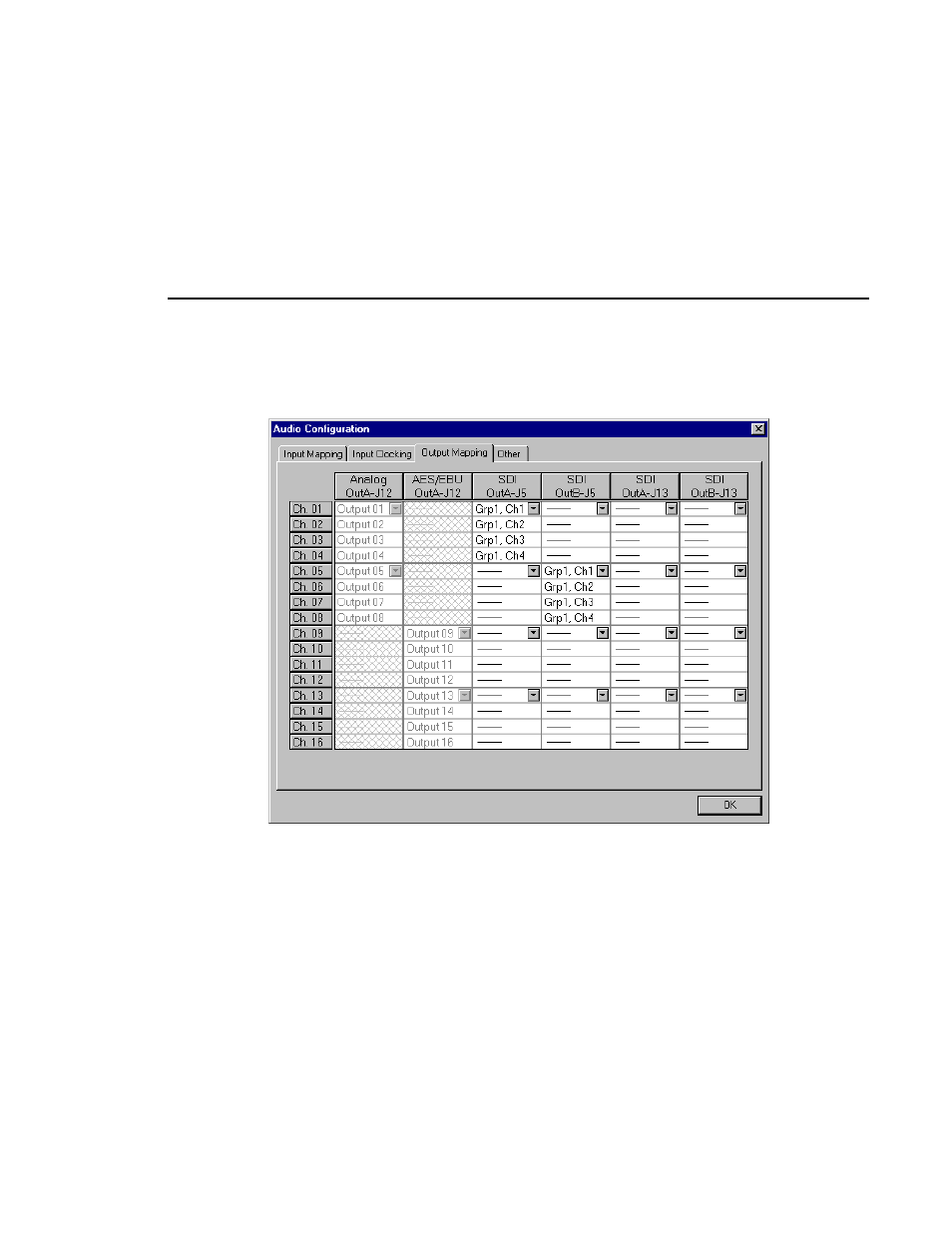
Figure 48. Audio Configuration dialog box, Output Mapping tab
The columns represent the sources to the sixteen channels on the input side and
the destinations from the sixteen channels on the output side. The examples in
Figure 47 and Figure 48 illustrate the system with a PAC 208 chassis allowing
the selection of analog channels 1–8 and digital channels 9–16. A PAC 216
chassis, however, provides sixteen analog inputs and outputs or sixteen digital
inputs and outputs. For the PAC 208, rows 9 through 16 of the analog channel
column, and rows 1 through 8 of the AES/EBU channel column, are cross-
hatched to indicate that these channels are not selectable. In Figure 48, in the
column labeled AES/EBU, rows 9–16 appear dimmed, indicating that this
audio type is always mapped and cannot be unmapped. Attempting to remap
this section results in an error message.