Command registers (read/write) for modbus rtu – Yaskawa G7 Modbus Communication User Manual
Page 42
42
Command Registers (Read/Write) for Modbus RTU
Command registers are those used to control the operation of the G7 drive either through a network interface (option card) or via serial
communication (defined as Modbus built into the drive’s keypad port or terminal strip). These registers are available during an active Run
command. It should be noted that multi-function digital inputs that are commanded over a communication network are logically OR’d with their
physical digital input terminal counterpart.
The “Address” column contains the register address in hexadecimal format. G7 drive registers are always referred to in hexadecimal format. The
“Function” column contains the register name. The “Bit” and “Description” columns contain the list of available bits for that register and a short
description of each. If the “Bit” column is empty, the register contains word data and individual bits have no meaning.
Please note that these Command Registers are different from those used in theCM090 Modbus TCP/IP Ethernet Option card. Refer to the
section toward the end of this chapter for more information on Modbus TCP/IP.
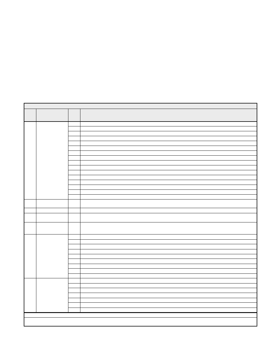
Table 4.1 Command Registers (Read/Write)
Addr.
Function
Bit
Description
0h
Run Command (0 = Stop, 1 = Run)
1h
Direction Command (0 = Forward, 1 = Reverse)
2h External
Fault
3h Fault
Reset
4h
Frequency Reference Source (0 = b1-01 Setting, 1 = Modbus communication)
5h
Run Command Source (0 = b1-02 Setting, 1 = Modbus communication)
6h
Multi-Function Digital Input Terminal S3. Function set by setting of H1-01
7h
Multi-Function Digital Input Terminal S4. Function set by setting of H1-02
8h
Multi-Function Digital Input Terminal S5. Function set by setting of H1-03
9h
Multi-Function Digital Input Terminal S6. Function set by setting of H1-04
Ah
Multi-Function Digital Input Terminal S7. Function set by setting of H1-05
Bh
Multi-Function Digital Input Terminal S8. Function set by setting of H1-06
Ch
Multi-Function Digital Input Terminal S9. Function set by setting of H1-07
Dh
Multi-Function Digital Input Terminal S10. Function set by setting of H1-08
Eh
Multi-Function Digital Input Terminal S11. Function set by setting of H1-09
0001h
Digital Input
Command
Fh
Multi-Function Digital Input Terminal S12. Function set by setting of H1-10
0002h
Frequency Reference
Setpoint
-
Scaling Dependent Upon o1-03 Setting
0006h
PID Setpoint
-
PID Setpoint
0007h
Analog Output FM
Setpoint
-
Sets the value of analog output terminal FM. (-1540 / -11VDC ~ 1540 / +11VDC)
0008h
Analog Output AM
Setpoint
-
Sets the value of analog output of terminal AM (-1540 / -11VDC ~ 1540 / +11VDC)
0h
Multi-Function Digital Output 1 (M1-M2)
1h
Multi-Function Digital Output 2 (M3-M4)
2h
Multi-Function Digital Output 3 (M5-M6)
3h
Multi-Function Digital Output 4 (P3-C3)
4h
Multi-Function Digital Output 5 (P4-C4)
5h Reserved
6h
Fault Contact Output Enable (1 = Enable bit 7)*
7h
Fault Contact Digital Output (MA, MB, MC)
0009h
Digital Output
Command
8h-Fh Reserved
0h Reserved
1h
PID Setpoint Enable (when set to “1”, use Register 0006h for the PID Setpoint)
2h–Bh
Reserved
Ch
Broadcast Data Terminal S5 Enable**
Dh
Broadcast Data Terminal S6 Enable**
Eh
Broadcast Data Terminal S7 Enable**
000Fh Command
Selection
Fh
Broadcast Data Terminal S8 Enable**
Note:
*
Overrides the standard functionality of the Fault Contacts. Use caution.
**
These bits must be set to “1” in order to use the Simultaneous Broadcast Register multi-function inputs S3, S4, S5 and S6 (bits 0Ch, 0Dh, 0Eh and
0Fh respectively). Refer to Table 4.2 Broadcast Registers.