Yaskawa G7 Modbus Communication User Manual
Page 65
65
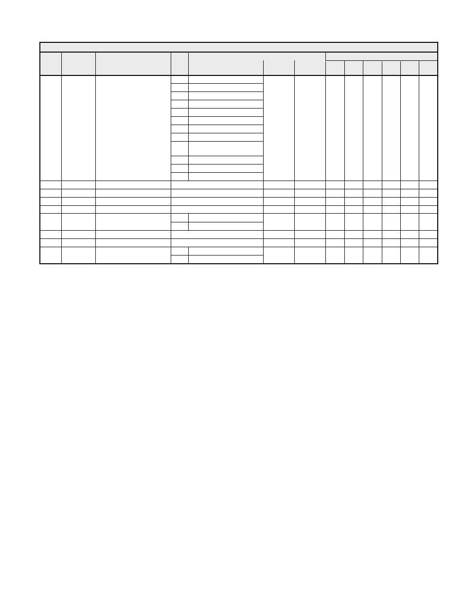
Table 4.10 “H” Parameters
Access Level
Name
Address
Description
Data
Range
Unit
Default
During
Run
V/f
V/f
w/PG
OLV
FV
OLV2
1Bh
Baseblock 2
1Ch
Motor 2 Selected
1Dh
Regenerating
1Eh
Restart Enabled
1Fh
Overload (OL1)
20h
OH Pre-alarm
30h
In Torque Limit
31h
In Speed Limit
32h
In Speed Limit (Torque
Control Only)
33h
Zero Servo Complete
37h
During Run 2
H2-01
040Bh
Digital Output Terminal
M1-M2 Function Selection
38h
drive Enable
1
0h
- - - - -
H2-02
040Ch
Terminal M3-M4 Selection
See
H2-01
1
1h
A A A A A
H2-03
040Dh
Terminal M5-M6 Selection
See
H2-01
1
2h
A A A A A
H2-04
040Eh Terminal
P3-C3
Selection
See
H2-01
1
06h
A A A A A
H2-05
040Fh Terminal
P4-C4
Selection
See
H2-01
1
10h
A A A A A
0 0-10
VDC
H3-01
0410h
Analog Input Terminal
A1 Signal Type Selection
1
-10 +10 VDC
1
0
A A A A A
H3-02
0411h
Terminal A1 Gain
0.0 ~ 1000.0 %
0.1 %
100.0 %
R
A
A
A
A
A
H3-03
0412h
Terminal A1 Bias
-100.0 ~ 100.0 %
0.1 %
0.0 %
R
A
A
A
A
A
0 0-10
VDC
H3-04
0413h
Analog Input Terminal
A3 Signal Type Selection
1
-10 +10 VDC
1
0
A A A A A