Yaskawa G7 Modbus Communication User Manual
Page 77
77
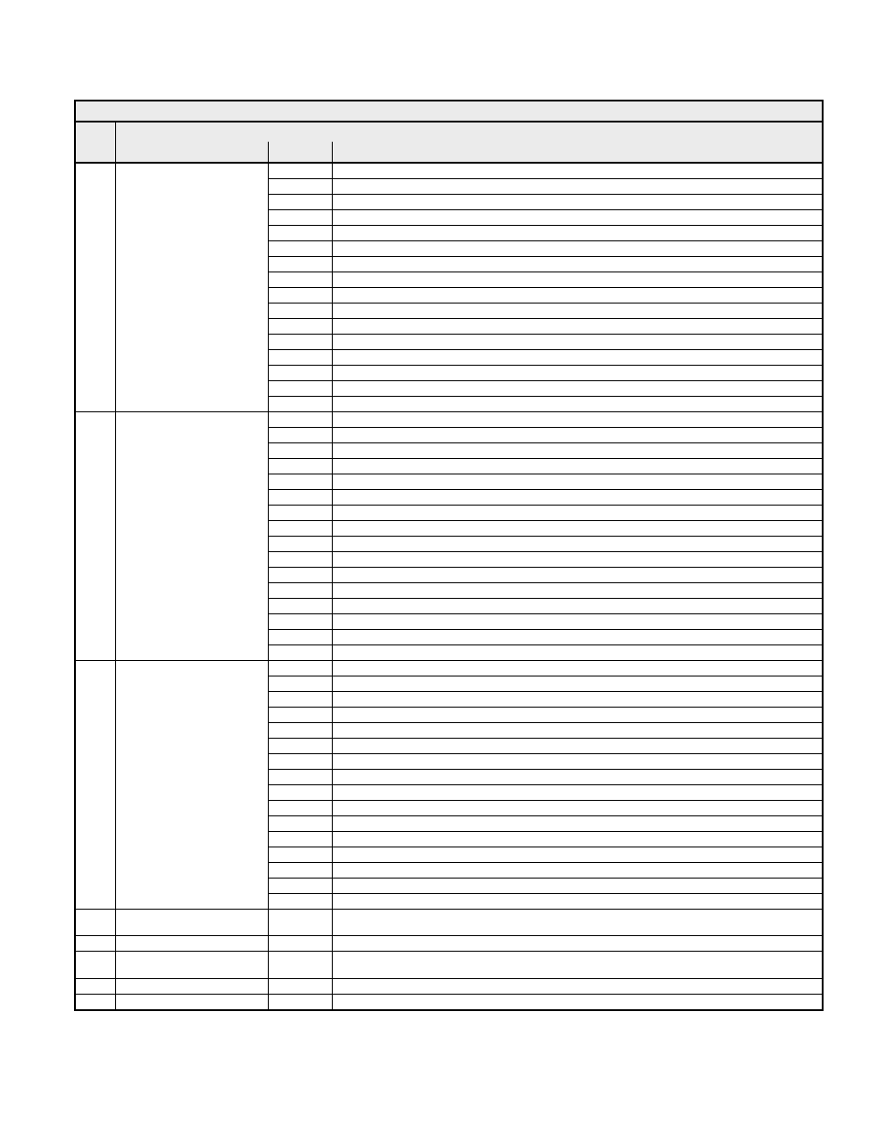
Table 4.15 Modbus TCP/IP Interface Registers (continued)
Addr
ess
Function
Bit
Description
0h
PUF - DC Bus Fuse Failure
1h
UV1 - Main Circuit Undervoltage
2h
UV2 - Control Power Undervoltage
3h
UV3 - Pre-charge Contactor Answerback Failure
4h Reserved
5h
GF - Ground Fault
6h OC
-
Overcurrent
7h
OV - Overvoltage
8h
OH - drive Overheat
9h
OH1 - Motor Overheat Alarm
Ah
OL1 - Motor Overload
Bh
OL2 - drive Overload
Ch
OL3 - Overtorque Detection 1
Dh
OL4 - Overtorque Detection 2
Eh
RR - Braking Resistor Failure
2009h Error
1
Fh
RH - Braking Resistor Overheat
0h
EF3 - External Fault 3
1h
EF4 - External Fault 4
2h
EF5 - External Fault 5
3h
EF6 - External Fault 6
4h
EF7 - External Fault 7
5h Reserved
6h Reserved
7h
OS - Overspeed
8h
DEV - Speed Deviation
9h
PGO - Encoder (PG) Feedback Loss
Ah
PF - Input Phase Loss
Bh
LF - Output Phase Loss
Ch
OH3 - Motor Overheat 1
Dh OPR
-
Operator
Disconnected
Eh
ERR - EEPROM Write Failure
200Ah Error
2
Fh
OH4 - Motor Overheat 2
0h
CE - Communication Loss
1h
BUS - Option Card Error
2h Reserved
3h Reserved
4h
CF - Loss of Motor Control
5h
SVE - Zero Servo Fault
6h
EF0 - Option Card External Fault
7h
FBL - PID Feedback Loss
8h
UL3 - Undertorque Detection 1
9h
UL4 - Undertorque Detection 2
Ah
OL7 - High Slip Braking Overload
Bh Reserved
Ch Reserved
Dh Reserved
Eh Reserved
200Bh Error
3
Fh
CPF – Control Board Hardware Fault
200Ch
Analog Input Terminal A1
Monitor
- Keypad
Monitor
U1-15
200Dh Digital Input Terminal Monitor
-
Digital Input Terminal Value (Bit Field of Terminals S1-S8)
200Eh
Analog Input Terminal A3
Monitor
- Keypad
Monitor
U1-17
200Fh
PG Count Channel 2 Monitor
-
Rolling Counter from 0 - 65,535
2010h
Inverter Flash ID
-
Lat 5 digits of the drive software number.