Profibus interface – ProSoft Technology ILX69-PBM User Manual
Page 18
Contents
ILX69-PBM ♦ CompactLogix or MicroLogix Platform
User Manual
PROFIBUS Master Communication Module
Page 18 of 124
ProSoft Technology, Inc.
February 4, 2015
3.2
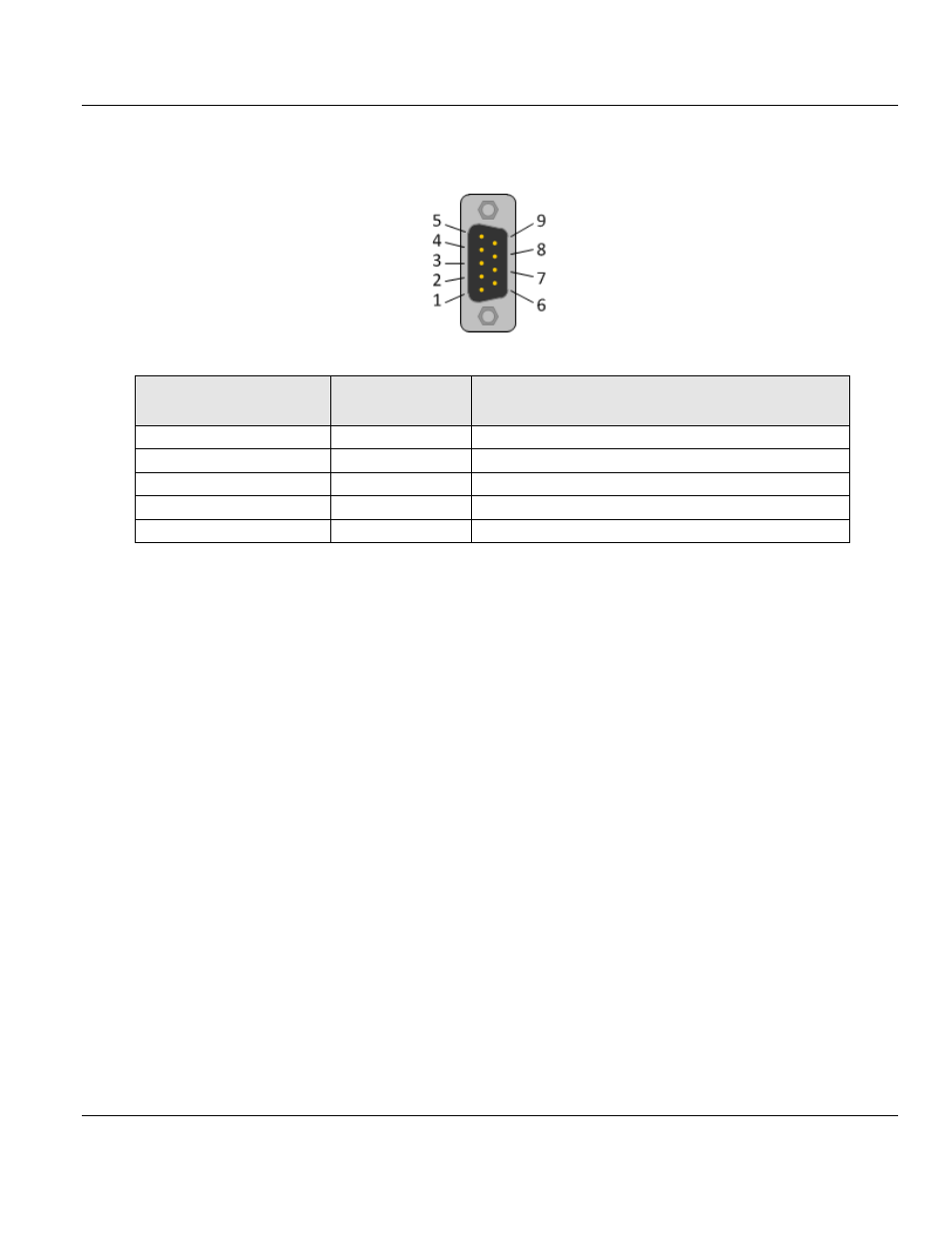
PROFIBUS Interface
PROFIBUS Interface (D-Sub female connector, 9 pin):
Connection with D-
Sub female connector
Signal
Description
3
RxD / TxD-P
Receive/Send Data-P, respectively connection B plug
4
CNTR-P
Repeater-Control
5
DGND
Data Ground
6
VP
Positive supply voltage
8
RxD / TxD-N
Receive/Send Data-N, respectively connection A plug
3.2.1 Wiring Instructions
Please ensure that termination resistors are available at both ends of the PROFIBUS
network cable. If special PROFIBUS connectors are being used, these resistors are often
found inside the connector and must be switched on at each end of the PROFIBUS network
cable.
For baud rates above 1.5 MBaud, use only special connectors for higher baud rates. These
include additional inductance.
It is not permitted to have T-stubs on PROFIBUS high baud rates. Use only a special cable
which is approved for PROFIBUS DP. Make a solid connection from the cable shield to
ground at every device and make sure that there is no potential difference between the
grounds at the devices.