I/o communication and memory map – ProSoft Technology ILX69-PBM User Manual
Page 64
Contents
ILX69-PBM ♦ CompactLogix or MicroLogix Platform
User Manual
PROFIBUS Master Communication Module
Page 64 of 124
ProSoft Technology, Inc.
February 4, 2015
6.2
I/O Communication and Memory Map
The following sections contain the I/O memory mappings of the ILX69-PBM. The I/O area is
used for communication status, command information, and cyclic I/O data.
6.2.1 I/O Arrays Overview
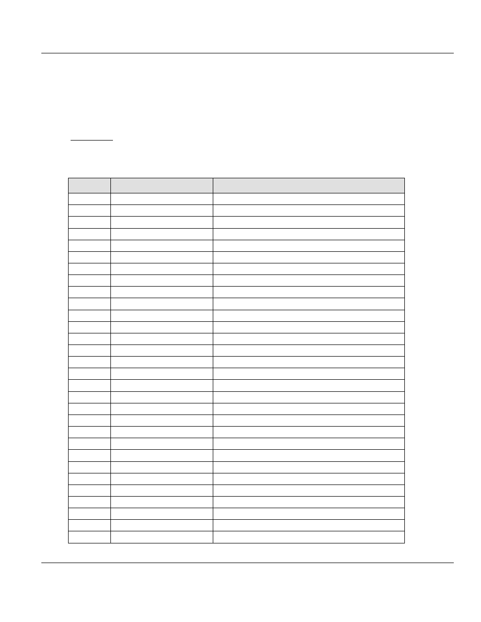
Input Array
Below is a summary of the register layout of the input area of the ILX69-PBM. The offset
values are defined in bytes.
Offset
Register Type
Name
0
Status Register
Module Status Bits
1
Status Register
Handshake Acknowledge Bits
2
Status Register
Block Transfer Out
3
Status Register
Block Transfer In
4
Firmware Revision
Minor Version
5
Firmware Revision
Major Version
6
Input Block Count
Input Block Count
7
Output Block Count
Output Block Count
8
Global State Field
Global Bits
9
Global State Field
DPM_State
10
Global State Field
Reserved[14], set to 0
24 to 39
Global State Field
Sl_cfg[16]
40 to 55
Global State Field
Sl_state[16]
56 to 71
Global State Field
Sl_diag[16]
72
Slave Diagnostics Field
Slave Address
73
Slave Diagnostics Field
Slave Diag Failure
74
Slave Diagnostics Field
Station Status_1
75
Slave Diagnostics Field
Station Status_2
76
Slave Diagnostics Field
Station Status_3
77
Slave Diagnostics Field
Master Address
78 to 79
Slave Diagnostics Field
Ident Number
80
DPV1 Alarm Indication
Alarm_Status
81
DPV1 Alarm Indication
Rem_Add
82
DPV1 Alarm Indication
Alarm_Cnt
83
DPV1 Alarm Indication
Slot_Number
84
DPV1 Alarm Indication
Seq_Nr
85
DPV1 Alarm Indication
Alarm_Type
86
DPV1 Alarm Indication
Alarm_Spec
87
DPV1 Alarm Indication
Reserved, set to 0
88 to 495
PROFIBUS Input Area
Inputs[408] (5712 bytes in block transfer)