ProSoft Technology ILX69-PBM User Manual
Page 65
ILX69-PBM ♦ CompactLogix or MicroLogix Platform
Contents
PROFIBUS Master Communication Module
User Manual
ProSoft Technology, Inc.
Page 65 of 124
February 4, 2015
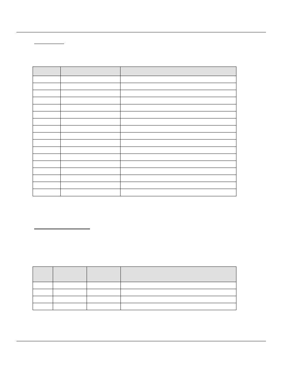
Output Array
Below is a summary of the register layout of the output area of the ILX69-PBM. The offset
values are defined in bytes.
Offset
Register Type
Name
0
Device Command Register
Command Bits
1
Device Command Register
Handshake Request Bits
2
Device Command Register
Block Transfer Out
3
Device Command Register
Block Transfer In
4
Slave Diagnostic
Slave Address
5
Slave Diagnostic
Function
6
Slave Diagnostic
Reserved, set to 0
7
Slave Diagnostic
Reserved, set to 0
8
Global Control Command
Slave_Address
9
Global Control Command
Control_Command
10
Global Control Command
Group_Select
11
Global Control Command
Reserved, set to 0
12
Reserved Register
Reserved, set to 0
13
Reserved Register
Reserved, set to 0
14
Reserved Register
Reserved, set to 0
15
Reserved Register
Reserved, set to 0
16 to 495
PROFIBUS Output area
Outputs[480] (5760 bytes in block transfer)
6.2.2 Input Array
Device Status Registers
The ILX69-PBM uses the first 4 bytes of the input area to transfer the device status register
information. The Device Status Registers contain the ILX69-PBM communication status and
command status. The input area mapping of this information is shown below.
Device Status Registers
Byte
Offset
Structure
Member
Data Type
Description
0
MSB
SINT
Module Status Bit
1
HAS
SINT
Handshake Acknowledge Bits
2
BTO
INT
Block Transfer Out
3
BTI
INT
Block Transfer In