Installing the module in the rack – ProSoft Technology MVI56E-DNPNET User Manual
Page 12
Contents
MVI56E-DNPNET ♦ ControlLogix Platform
User Manual
DNPNET Ethernet Client/Server Communication Module
Page 12 of 140
ProSoft Technology, Inc.
February 13, 2015
Note:
If you are installing the module in a remote rack, you may prefer to leave the Setup pins jumpered. That
way, you can update the module’s firmware without requiring physical access to the module.
1.5
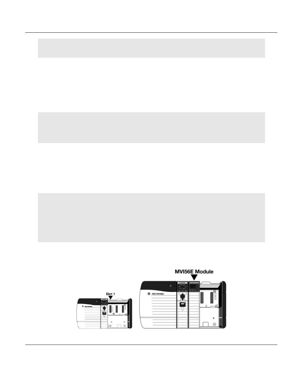
Installing the Module in the Rack
Make sure your ControlLogix processor and power supply are installed and configured,
before installing the MVI56E-DNPNET module. Refer to your Rockwell Automation product
documentation for installation instructions.
Warning:
You must follow all safety instructions when installing this or any other electronic devices. Failure to
follow safety procedures could result in damage to hardware or data, or even serious injury or death to
personnel. Refer to the documentation for each device you plan to connect to verify that suitable safety
procedures are in place before installing or servicing the device.
After you have checked the placement of the jumpers, insert the MVI56E-DNPNET into the
ControlLogix chassis. Use the same technique recommended by Rockwell Automation to
remove and install ControlLogix modules.
You can install or remove ControlLogix system components while chassis power is applied
and the system is operating. However, please note the following warning.
Warning:
When you insert or remove the module while backplane power is on, an electrical arc can occur. An
electrical arc can cause personal injury or property damage by sending an erroneous signal to the system’s
actuators. This can cause unintended machine motion or loss of process control. Electrical arcs may also cause
an explosion when they happen in a hazardous environment. Verify that power is removed or the area is non-
hazardous before proceeding.
Repeated electrical arcing causes excessive wear to contacts on both the module and its mating connector.
Worn contacts may create electrical resistance that can affect module operation.
1
Align the module with the top and bottom guides, and then slide it into the rack until the
module is firmly against the backplane connector.