Module, and controllogix processor – ProSoft Technology MVI56E-DNPNET User Manual
Page 82
Contents
MVI56E-DNPNET ♦ ControlLogix Platform
User Manual
DNPNET Ethernet Client/Server Communication Module
Page 82 of 140
ProSoft Technology, Inc.
February 13, 2015
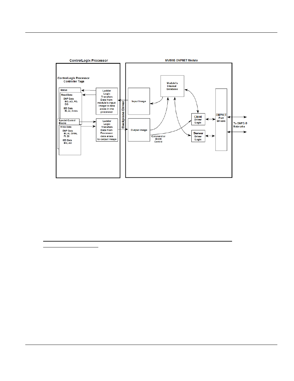
The following illustration shows the data transfer method used to move data between the
ControlLogix processor, the MVI56E-DNPNET module and the DNP3 Ethernet Network.
All data transferred between the module and the processor over the backplane is through
the input and output images. Ladder logic is needed in the ControlLogix processor to
interface the input and output image data with data defined in the Controller Tags. All data
used by the module is stored in its internal databases. These databases are defined as a
virtual DNPNET data tables with addresses from 0 to the maximum number of points for
each data type.
Data Flow Between the DNP3 Ethernet network, MVI56E-DNPNET Module, and
ControlLogix Processor
The following topics describe the flow of data between the two pieces of hardware
(ControlLogix processor, and the MVI56E-DNPNET module) and other nodes on the DNP3
Ethernet network under the module’s different operating modes.
The module is configured to emulate a DNP3 Ethernet Client device and/or a DNP3
Ethernet server device. The operation of each depends on the user’s configuration. The
following topics discuss the operation of each mode.