Atmosphere, User manual – Atlas Sound Atmosphere C-ZSV Zone, Source, and Volume Wall Controller (Black) User Manual
Page 11
Atmosphere
User Manual
AtlasIED.com
TELEPHONE: (800) 876-3333
1601 JACK MCKAY BLVD.
ENNIS, TEXAS 75119 U.S.A.
– 11 –
3. Balanced Line Outputs
Zone outputs 1-4 (AZM4) or 1-8 (AZM8) are to connect to balanced line inputs, primarily for amplifiers, such as the Atmosphere AZA amplifiers, that
power zone speakers.
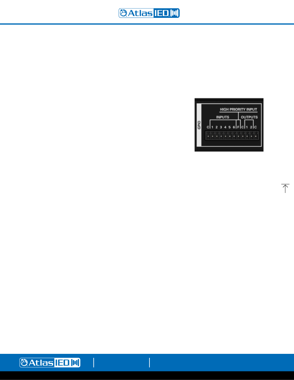
4. GPIO (General Purpose Input Output Ports)
The 3.5mm 12-way GPIO Euro block contains:
•
3 x Common “C” – these are all tied to common and can be used for any terminal wiring.
•
6 x (1 - 6) control inputs – configured individually in the UI as CC (Contact Closure) (Normally Open) or 1.5-12Vdc trigger.
The 6 control inputs can:
• Recall
a
routine
• Recall
a
scene
• Trigger
message
playback
• Run
a
bell
schedule
• Trigger
a
GPO
preset
• Combine
room
•
1 x Terminal “F” High Priority “HP” input function.
The High-Priority input can:
• Mute
all
zones
•
Set all zones and group levels
•
Lock and alert accessory controllers
•
Play a message one time or on a repeated basis
•
2 (GPO-1 & GPO-2) Control Outputs - Voltage triggers are individually named and assignable in GPIO Outputs page and configured in
Output Presets page. The Output Presets page includes 5 types of voltage trigger settings that can be configured: Logic H,
Logic L, Toggle, Pulse H, and Pulse L, along with adjustable Pulse Time from .1-10.0 sec, a common “C” terminal for output ports
1 & 2 for external equipment interfacing.
5. Accessory Ports
RJ45 (not-Ethernet) bus-ports A & B (AZM4) or A, B, C & D (AZM8) are used for connecting
Atmosphere Plug and Play accessories. All accessories are recognized by the UI automatically when plugged in and can be assigned to any zone.
Multiple bus-ports are provided to allow more accessories to be used and to make it easier for installers to create cable homeruns.
To guarantee good performance of all connected accessories, follow these rules:
1.
Use CAT5e or CAT6 (non-shield) cable to connect accessories to the host processor bus-port.
2. Up to 8 Accessories can be daisy chained from a single port.
3. Up to 16 Accessories can be connected to a single AZM, (AZM4 or AZM8).
4. The maximum cable length from the AZM to the last accessory on the chain is 1000’(305m).
5. One Audio Wall Plate (A-XLR, A-RCA, A-BT) can be used per bus-port.
Note:
See “Plug and Play Accessories Connection Rules” for more details.
Note:
A maximum of 8 X-ANS accessories can be used per AZM.
6. Network
Connect to LAN where device is installed. The AZM default IP is set to DHCP and, when terminated to a router with DHCP enabled, will
display the IP address on the front panel display.
7.
AC Power
AC Power Input – IEC connector, 100-240VAC ~ 50-60 Hz, universal power supply.