Method 3 - access point connection, Software overview, Dashboard – Atlas Sound Atmosphere C-ZSV Zone, Source, and Volume Wall Controller (Black) User Manual
Page 14: Features, Atmosphere, User manual
Atmosphere
User Manual
AtlasIED.com
TELEPHONE: (800) 876-3333
1601 JACK MCKAY BLVD.
ENNIS, TEXAS 75119 U.S.A.
– 14 –
Method-3 - Access Point Connection (Built-in WiFi creates a local wireless network for connection)
•
From the front panel menu enable Access Point Mode (Network>WiFi>Change Mode>Access Pt, then confirm change).
•
The unit will now broadcast an SSID (AtlasIED_AZM will be the default SSID) that can be found using WiFi enabled devices.
•
Select the now available network from the settings page on your device and connect. (The default password is AtlasIED.
This can be changed in the user interface).
•
Using a web browser on the device, navigate to the IP address that appears on the AZM front panel screen using the address
bar located in the web browser.
Software Overview (in order of toolbar, left to right)
Dashboard
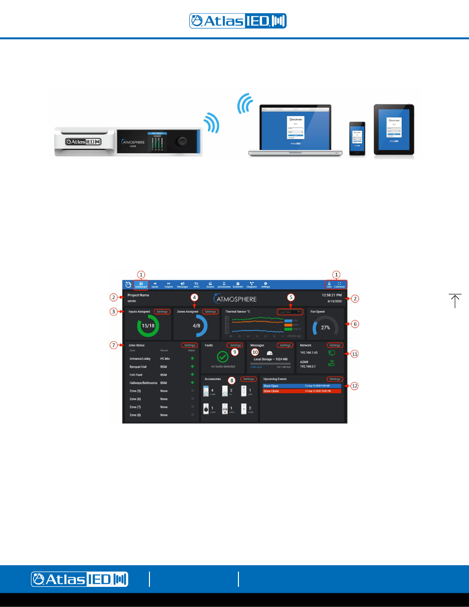
The Dashboard is the user page to monitor the AZM system wide activity. It provides quick links to interrogate and fix settings.
Features
1.
The Dashboard is the first tool on the UI navigation toolbar. Select to open. To the far right, there is a User link to settings page, and an option
for Full Screen view, if desired. The background has a dark or light Theme setting that can be selected when logging in or otherwise selected
in settings under the Theme page.
2. This area displays the project and user’s name that is entered under the settings toolbar on the Project Settings page to the left. On the right,
the Time & Date is also set up under the settings toolbar on the Clock Settings page.
3. Input Sources Assigned - displays a Green LED style indicator for each of the inputs routed to a zone. An input source will also be counted as
consumed if it has been given a name or is part of a scene.
4. Zones Assigned - displays a Blue LED style indicator for each of the zone outputs that are assigned to a source.
5. Thermal Sensor – this is the output of the three monitored heat sensors: PSU (power supply unit), Micro (microprocessor), and Analog I/O.
The read-out can be viewed by Last Hour, Last Day, Last Week, or Last Month.
6. An internal fan will turn on automatically if necessary and speed is displayed as a visual graphic and corresponding percent. Fan speed is
dynamically regulated by monitoring temperature. The airflow direction is front to rear.