Altera Arria V Avalon-MM User Manual
Page 146
As this figure illustrates, the
reconfig_to_xcvr[
<n>
70-1:0]
and
reconfig_from_xcvr[
<n>
46-1:0]
buses connect the two components. You must provide a 100–125 MHz free-running clock to the
mgmt_clk_clk
clock input of the Transceiver Reconfiguration Controller IP Core.
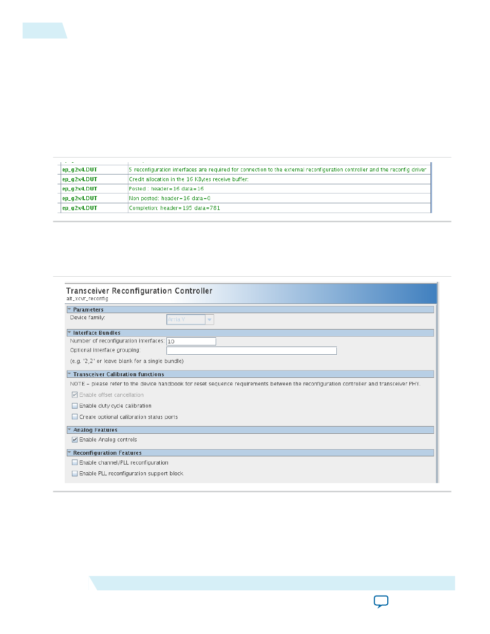
Initially, each lane and TX PLL require a separate reconfiguration interface. The parameter editor reports
this number in the message pane. You must take note of this number so that you can enter it as a
parameter value in the Transceiver Reconfiguration Controller parameter editor. The following figure
illustrates the messages reported for a Gen2 ×4 variant. The variant requires five interfaces: one for each
lane and one for the TX PLL.
Figure 12-2: Number of External Reconfiguration Controller Interfaces
When you instantiate the Transceiver Reconfiguration Controller, you must specify the required Number
of reconfiguration interfaces as the following figure illustrates.
Figure 12-3: Specifying the Number of Transceiver Interfaces for Arria V and Cyclone V Devices
The Transceiver Reconfiguration Controller includes an Optional interface grouping parameter.
Transceiver banks include six channels. For a ×4 variant, no special interface grouping is required because
all 4 lanes and the TX PLL fit in one bank.
Note: Although you must initially create a separate logical reconfiguration interface for each lane and TX
PLL in your design, when the Quartus II software compiles your design, it reduces the original
12-2
Connecting the Transceiver Reconfiguration Controller IP Core
UG-01105_avmm
2014.12.15
Altera Corporation
Transceiver PHY IP Reconfiguration