Channel placement in arria v devices, Pipe interface signals – Altera Arria V Avalon-MM User Manual
Page 58
For more comprehensive information about Arria V transceivers, refer to the Transceiver Banks section in
the Transceiver Architecture in Arria V Devices.
Related Information
Channel Placement in Arria V Devices
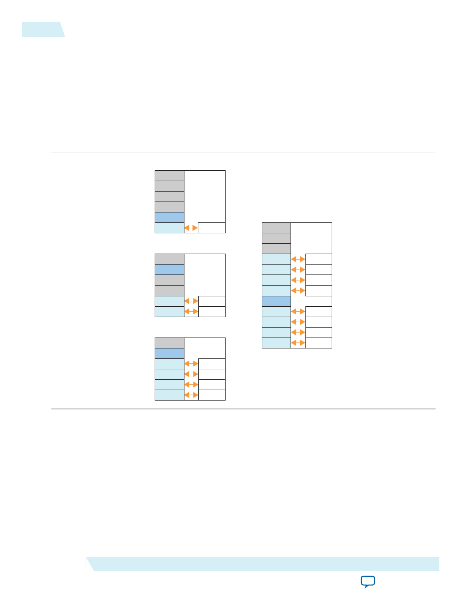
Figure 4-10: Arria V Gen1 and Gen2 Channel Placement Using the CMU PLL
In the following figures the channels shaded in blue provide the transmit CMU PLL generating the high-
speed serial clock.
Ch5
Ch3
Ch2
Ch1
Ch0
CMU PLL
PCIe Hard IP
Ch0
Ch1
Ch5
Ch3
Ch2
Ch1
Ch0
CMU PLL
PCIe Hard IP
Ch0
Ch1
Ch2
Ch3
Ch5
Ch3
Ch2
Ch1
Ch0
CMU PLL
Ch0
Ch1
Ch2
Ch3
Ch11
Ch9
Ch8
Ch7
Ch6
Ch10
PCIe Hard IP
Ch5
Ch6
Ch7
Ch4
Ch5
Ch3
Ch2
CMU PLL
Ch0
Ch4
PCIe Hard IP
x1
x8
x2
x4
Ch0
You can assign other protocols to unused channels the if data rate and clock specification exactly match
the PCIe configuration.
PIPE Interface Signals
These PIPE signals are available for Gen1 and Gen2 variants so that you can simulate using either the
serial or the PIPE interface. Simulation is much faster using the PIPE interface because the PIPE
simulation bypasses the SERDES model . By default, the PIPE interface is 8 bits for Gen1 and Gen2. You
can use the PIPE interface for simulation even though your actual design includes a serial interface to the
internal transceivers. However, it is not possible to use the Hard IP PIPE interface in hardware, including
probing these signals using SignalTap
®
II Embedded Logic Analyzer.
4-28
Channel Placement in Arria V Devices
UG-01105_avmm
2014.12.15
Altera Corporation
Interfaces and Signal Descriptions