Figure 6-1: reset controller block diagram – Altera Arria V Avalon-MM User Manual
Page 99
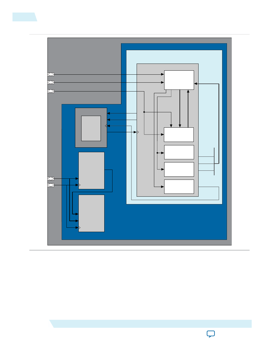
Figure 6-1: Reset Controller Block Diagram
Example Design
altpcie_dev_hip_<if>_hwtcl.v
altpcied_<dev>_hwtcl.sv
Transceiver Hard
Reset Logic/Soft Reset
Controller
Configuration Space
Sticky Registers
Datapath State
Machines of
Hard IP Core
SERDES
Configuration Space
Non-Sticky Registers
reset_status
pld_clk
pin_perst
npor
refclk
srst
crst
l2_exit
hotrst_exit
dlup_exit
pld_clk_inuse
Hard IP for PCI Express
fixed_clk
(100 or 125 MHz)
reconfig_xcvr_clk
mgmt_rst_reset
reconfig_busy
Transceiver
Reconfiguration
Controller
reconfig_xcvr_clk
reconfig_busy
reconfig_xcvr_rst
pcie_reconfig_
driver_0
altpcie_<dev>_hip_256_pipen1b.v
altpcie_rs_serdes.v
coreclkout_hip
coreclkout_hip
top.v
tx_digitalrst
rx_analogrst
rx_digitalrst
rx_freqlock
rx_signaldetect
rx_pll_locked
pll_locked
tx_cal_busy
rx_cal_busy
Chaining
DMA
(APPs)
reconfig_clk
mgmt_rst_reset
6-2
Reset and Clocks
UG-01105_avmm
2014.12.15
Altera Corporation
Reset and Clocks