Setup elements, Board settings dip switch, Setup elements –21 – Altera 100G Development Kit, Stratix V GX Edition User Manual
Page 29: Board settings dip switch –21
Chapter 2: Board Components
2–21
Configuration, Status, and Setup Elements
August 2012
Altera Corporation
100G Development Kit, Stratix V GX Edition
Reference Manual
Setup Elements
The development board includes several different kinds of setup elements. This
section describes the following setup elements:
■
Board settings DIP switch
■
Push buttons
■
Board jumpers
Board settings DIP switch
The board settings DIP switch (SW3) controls various features specific to the board
and the MAX
II CPLD EPM2210 System Controller logic design.
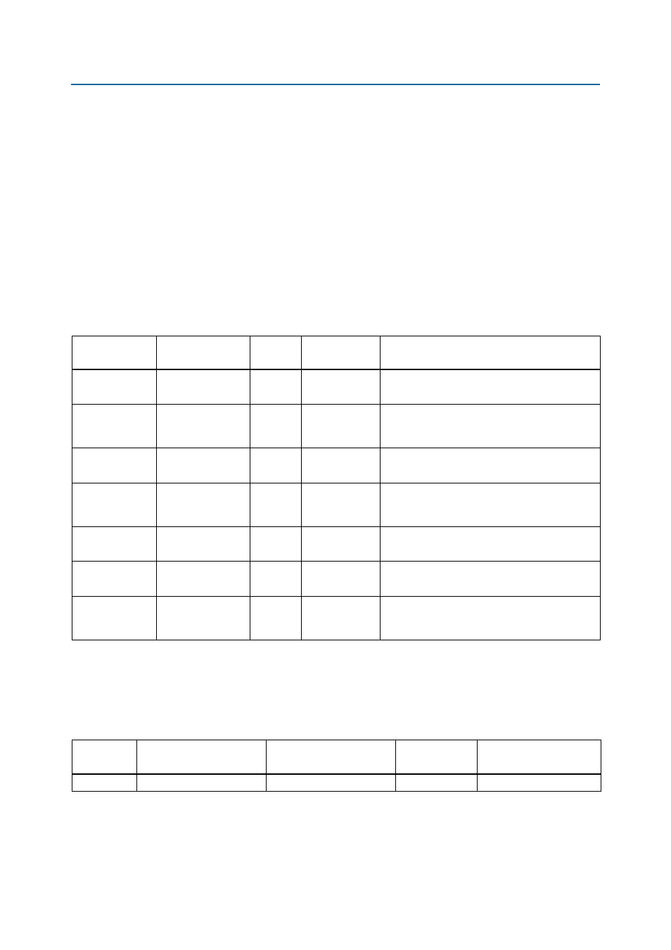
lists the board settings DIP switch controls and descriptions.
lists the board settings DIP switch component reference and
manufacturing information.
Table 2–9. Board Settings DIP Switch Controls
Board Reference
(SW3)
Schematic Signal
Name
I/O
Standard
Description
1
USB_DISABLEn
2.5-V
1: Enabled
0: Disabled
Disables the on-board USB-Blaster II.
2
DIFFCLKA_SEL
2.5-V
1: SMA input
0: PLL input
Selects SMA or PLL for the differential clock that
goes to the global clock inputs of clock A tree
structure.
3
REFCLKA_SEL
2.5-V
1: SMA input
0: PLL input
Selects SMA or PLL that goes to the transceivers
of clock A tree structure.
4
DIFFCLKB_SEL
2.5-V
1: SMA input
0: PLL input
Selects SMA or PLL for the differential clock that
goes to the global clock inputs of clock B tree
structure.
5
REFCLKB_SEL
2.5-V
1: SMA input
0: PLL input
Selects SMA or PLL that goes to the transceivers
of clock B tree structure.
6
CLK644_EN
2.5-V
1: Enabled
0: Disabled
Enables the 644.53125-MHz clock.
7
SECURITY
2.5-V
1: Enabled
0: Disabled
Turns on configuration security. When enabled,
the FPGA cannot be accessed via JTAG if the
device has already been programmed by the PFL.
Note to
:
(1) When the switch is in the OFF position, a logic 1 is selected while in the ON position, a logic 0 is selected.
Table 2–10. Board Settings DIP Switch Component References and Manufacturing Information
Board
Reference
Device Description
Manufacturer
Manufacturer
Part Number
Manufacturer Website
SW3
DIP switch
Grayhill Corporation
76SB08ST