Push buttons, Board jumpers, Push buttons –22 board jumpers –22 – Altera 100G Development Kit, Stratix V GX Edition User Manual
Page 30
2–22
Chapter 2: Board Components
Configuration, Status, and Setup Elements
100G Development Kit, Stratix V GX Edition
August 2012
Altera Corporation
Reference Manual
Push Buttons
Board reference S1 is the CPU reset push button, CPU_RESET, which is an input to the
Stratix V GX device. The CPU_RESET is the master reset signal for the FPGA design
loaded into the Stratix V GX device. You must enable the CPU_RESET signal within the
Quartus II software for this reset function to work. Otherwise, the CPU_RESET acts as a
regular I/O pin. When you enable this signal in the Quartus II software, and then set
to logic 1 on the board, this push button resets every register within the FPGA.
Board reference S7 is the reset push button, RESET, which is an input to the MAX II
CPLD EPM2210 System Controller. This reset signal is the default reset for the CPLD
logic. This signal forces a FPGA reconfiguration from the flash memory.
Board references S5, S6, and S8 are push buttons for MAX II+Flash FPP configuration.
Use the PGM_SEL push button (S8) to select the configuration programming image
stored in the flash memory.
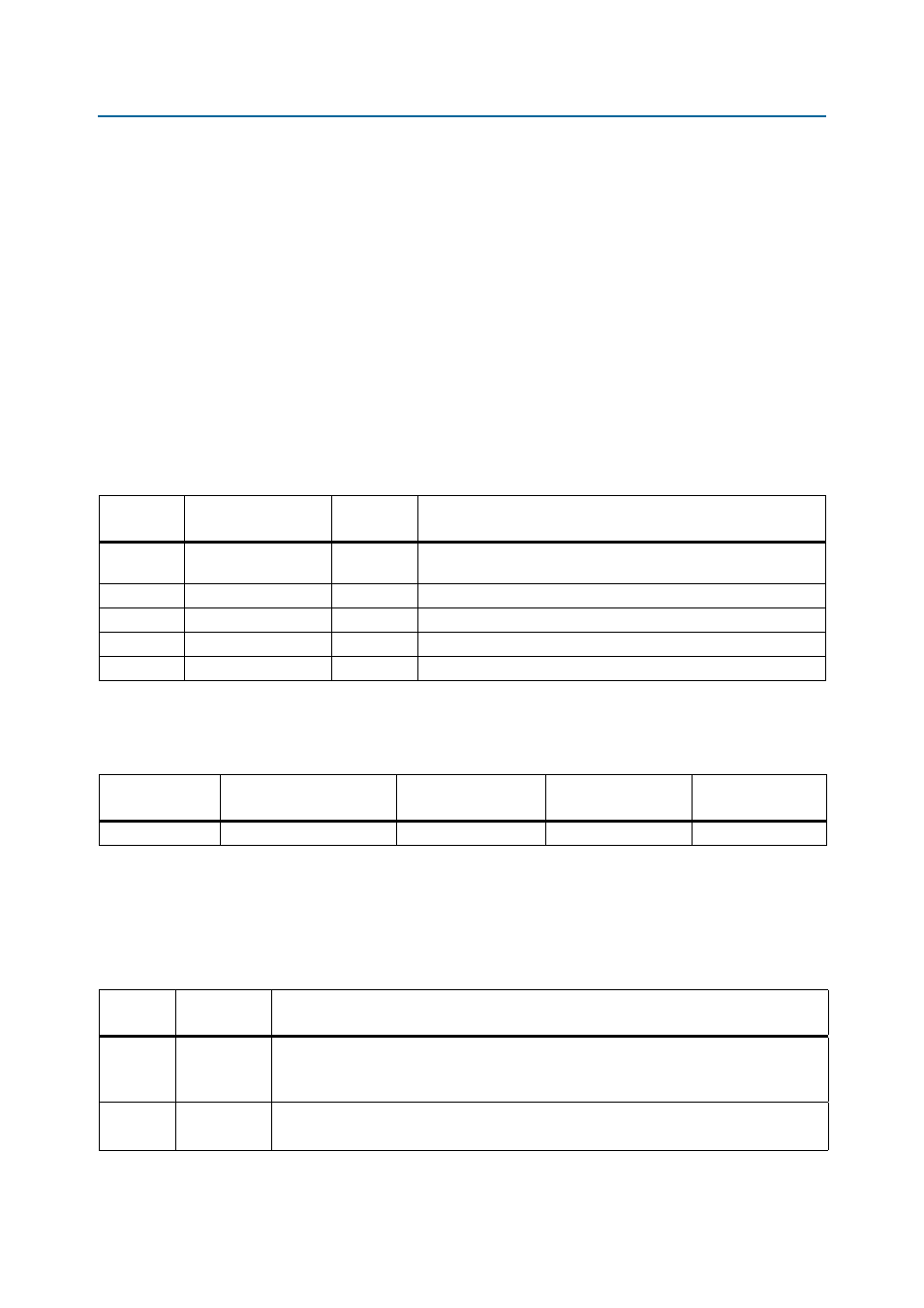
lists the push buttons references, names, and functional descriptions.
lists the push buttons component references and the manufacturing
information.
Board Jumpers
The board jumpers control feature specific to the JTAG chain and the MAX
II CPLD
EPM2210 System Controller logic design.
lists the board jumper references,
names, and functional descriptions.
Table 2–11. Push Buttons Signal Names and Functions
Board
Reference
Schematic Signal
Name
I/O Standard
Description
S1
CPU_RESET
2.5-V
Reset signal for the FPGA and MAX II CPLD EPM2210 System
Controller.
S5
LOAD
2.5-V
Initiates loading of the FPGA.
S6
FACTORY
2.5-V
Initiates loading of factory design into the FPGA.
S7
RESET
2.5-V
User reset signal for the MAX II CPLD EPM2210 System Controller.
S8
PGM_SEL
2.5-V
Selects between two .pof files (factory or user) stored in the flash.
Table 2–12. Push-Buttons Component References and Manufacturing Information
Board Reference
Device Description
Manufacturer
Manufacturer
Part Number
Manufacturer
Website
S1, S5–S8
Push buttons
Panasonic Corporation
EVQPAC07K
Table 2–13. Board Jumpers
Board
Reference
Schematic
Signal Name
Description
J62
MAX_JTAG_EN
■
Jumper installed – includes the MAX II CPLD device (U59) in the JTAG programming chain.
■
Jumper removed – removes the MAX II CPLD device (U59) from the JTAG programming
chain.
J9
FAN BYPASS
■
Jumper installed – fan is always on.
■
Jumper removed – MAX II CPLD EPM2210 System Controller controls the fan speed.