2 alarm input port, 3 alarm output port, Alarm input port – AGI Security SYS-HC0851S2 User Manual
Page 60: Alarm output port
51
Voltage current;500mA.
+12V
Rated current.
Voltage current;500mA.
Earth cable.
485 A/B
485 communication port. They are used to control devices such as
decoder.
120Ω should be parallel connected between A, B lines if
there are too many PTZ decoders.
T+,T-,R+,R-
They are four-wire full-duplex RS485 port
T+ T-: output wire
R+ R-: input wire
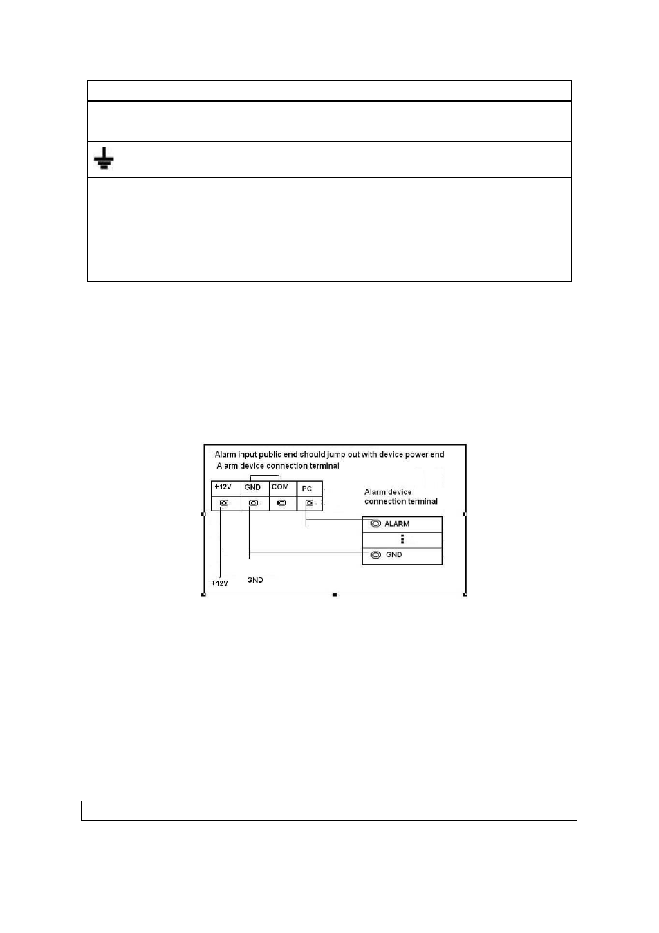
3.7.2 Alarm Input Port
Please refer to the following sheet for more information.
Grounding alarm inputs. Normal open or Normal close type)
Please parallel connect COM end and GND end of the alarm detector ( Provide
external power to the alar m detector).
Please parallel connect the Ground of the DVR and the ground of the alarm detector.
Please connect the NC port of the alarm sensor to the DVR alarm input(ALARM)
Use the same ground with that of DVR if you use external power to the alarm device.
Figure 3-2
3.7.3 Alarm Output Port
Provide external power to external alarm device.
To avoid overloading, please read the following relay parameters sheet carefully.
RS485 A/B cable is for the A/B cable of the PTZ decoder.
T+,T-,R+,R- are four-wire double duplex RS485 port.
T+ T-: output wire
R+ R-: input wire
Relay Specification
M odel:
JRC-27F