ARRIS DCT5100 Installation Manual User Manual
Page 18
2-2
Overview
DCT5100 Installation Manual
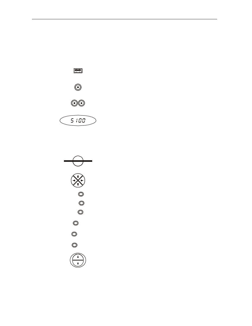
Table 2-1 describes the front-panel controls and LEDs:
Table 2-1
Front panel
Key Feature
Function
1
USB
The Universal Serial Bus (USB) connector is used to support
devices such as keyboards, joysticks, scanners, disk storage,
PCs, printers, and digital cameras.
2
VID EO IN
The
VIDEO IN
connector accepts baseband video from a VCR,
camcorder, or other video device.
3
L AUDIO IN R
This audio input connector pair accepts audio from a VCR,
camcorder, or other audio device.
4
P
M UTE
MSGS.
ON
REMOTE
A/B
Displays the channel number or time of day.
There are four indicator lights on the LED screen:
MSGS. — the DCT5100 has received messages for you to read
ON — the DCT5100 is powered on
A/B — the RF bypass is active
REMOTE — the remote control is in use
5
SMART CARD
This interface is intended to support electronic commerce
activity utilizing a smart card. Contact your service provider for
availability.
6
CURSOR
Moves the cursor around the program guide and menu screens.
7
MENU
Displays the main menu.
8
POW ER
Turns the device on or off.
9
IN FO
Displays the current channel and program information (not
supported by all applications).
10
A/B
Use to manually enable the RF bypass function. You must have
a cable-ready TV for this function to operate.
11
SELEC T
Selects menu options, pay-per-view events or programs from
the program guide.
12
GUID E
Displays the program guide.
13
CHANNEL
Changes the channels by moving up or down.