Dct5100 installation manual, Figure 3-3 audio system cabling, Installation 3-5 – ARRIS DCT5100 Installation Manual User Manual
Page 28: Dct 5100 vcr digital receiver, Either/or
Installation 3-5
DCT5100 Installation Manual
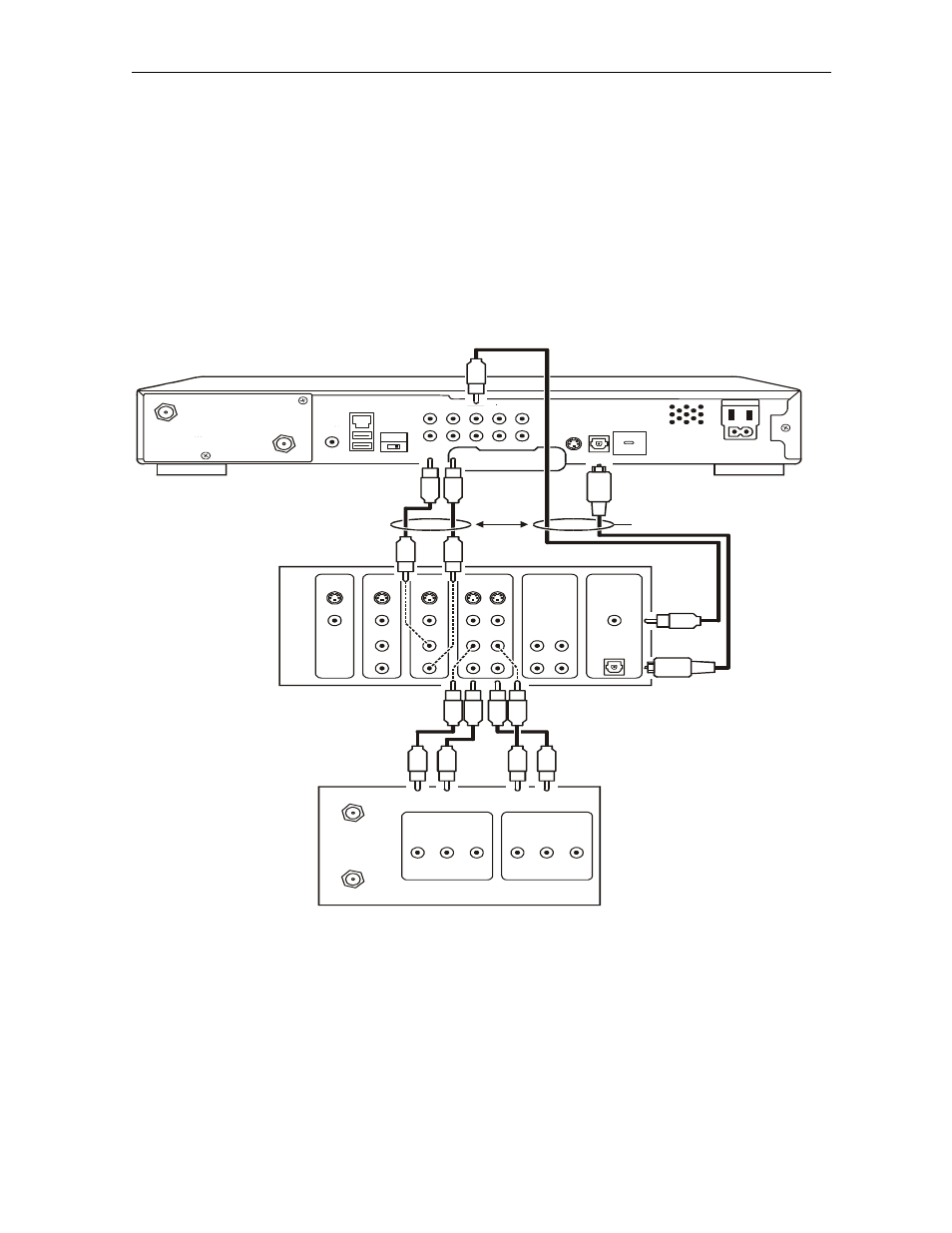
The VCR and TV receive their audio/video signals from the currently selected input device on the
digital receiver. This is important when the subscriber has another audio/video device such as a
DVD player, a secondary VCR, a CD player, or other electronic component. It is recommended
that you connect the TV to the monitor output so On-Screen menus associated with the receiver
can be displayed. (In many cases the receivers themselves have interactive on-screen menus).
Figure 3-3 illustrates the DCT5100 interfacing directly to a digital receiver:
Figure 3-3
Audio system cabling
To TV
CABLE/
ANTENNA IN
OUTPUT
AUDIO
L
R
VIDEO
INPUT
AUDIO
L
R
VIDEO
MONITOR
DVD
AV #2
AV #1
TAPE
IN
IN
S-VIDEO
VIDEO
RIGHT
LEFT
OUT
DIGITAL
COAXIAL
IN
OUT
OPTICAL
IN
OUT
ETHERNET
USB
HPNA
AUDIO IN
AUDIO
OUT
VIDEO
IR
R
IN
R
L
OUT
S-VIDEO
IEEE 1394
OPTICAL
SPDIF
SPDIF
L
Y
Pb
Pr
TV
Pass Card
SWITCHED
105-125V
60Hz
4A MAX
500W MAX
CONVENIENCE
OUTLET
TO
TV/VCR
CABLE
IN
DCT 5100
VCR
Digital Receiver
either/or
either/or
If your stereo receiver has the ability to check both the baseband and SPDIF ports for appropriate
channels, you will want to connect both the baseband and SPDIF connections. Otherwise, do not
connect both the baseband left/right RCA connections and the RCA SPDIF digital connection.
The baseband connections are not necessary because the SPDIF port carries audio for both
digital and analog channels providing for a single audio interface.