Rf bypass switch option, Key item function, Dct5100 installation manual – ARRIS DCT5100 Installation Manual User Manual
Page 20: For future use. 14, Connector, Figure 2-3 rf bypass switch option, Cêçã=å~ääé=çìíäéí qç=qs, 4 overview
2-4
Overview
DCT5100 Installation Manual
Key Item
Function
9
USB
The Universal Serial Bus (USB) supports such devices as
keyboards, joysticks, scanners, disk storage, PCs, printers, and
digital cameras.
10
HPNA
HPNA connector enables you to connect your DCT5100 to
computers within your home using existing telephone lines.
(Optional.)
11
AUDIO
OUT
R
L
Left and right audio RCA jacks used for stereo audio output.
12
Y
Pb
Pr
RCA jack connectors used to deliver component video.
13
TV
Pass Card
For future use.
14
S-VIDEO
Coaxial cable connector used to deliver high quality video to
external devices that accept S-Video inputs, such as a high-end
VCR or TV.
15
OPTICAL
SPDIF
The
OPTICAL
SPDIF
connector
is an optical digital output
connection that carries Dolby Digital 5.1 audio or PCM audio.
16
IEEE 1394
This high-speed data interface connector will support PCs,
entertainment system devices, data storage, and future high
definition TVs. (Optional.)
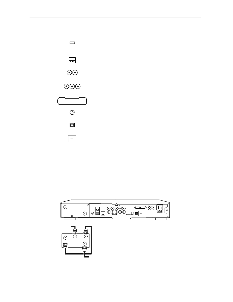
RF Bypass Switch Option
The RF Bypass switch option supports modulated/baseband video and audio outputs for a
variety of configurations that enable you to meet the needs of individual subscribers. The RF
Bypass causes the cable signal to pass the DCT5100 and go directly to a TV or VCR. Figure 2-3
illustrates the RF Bypass switch option:
Figure 2-3
RF Bypass switch option
ETHERNET
USB
HPNA
AUD IO IN
AUD IO
OUT
VIDEO
IR
R
IN
R
L
OUT
S-VIDEO
IEEE 1394
OPTICAL
SPD IF
PRINTER
SPD IF
L
Y
Pb
Pr
TV
Pass C ard
SWITCHED
105-125V
60Hz
4A MAX
500W MAX
CONVENIENCE
OUTLET
CABLE
IN
TO
TV/VCR
CABLE
IN
CONV
OUT
RF
OUT
CONV
IN
cêçã=Å~ÄäÉ=çìíäÉí
qç=qs