Rf bypass switch cabling diagrams, On the rf bypass switch, Dct 5100 – ARRIS DCT5100 Installation Manual User Manual
Page 26: Tv vcr (optional), Dct5100 installation manual, Figure 3-2 rf bypass switch, Installation 3-3, Conv out, Conv in
Installation 3-3
DCT5100 Installation Manual
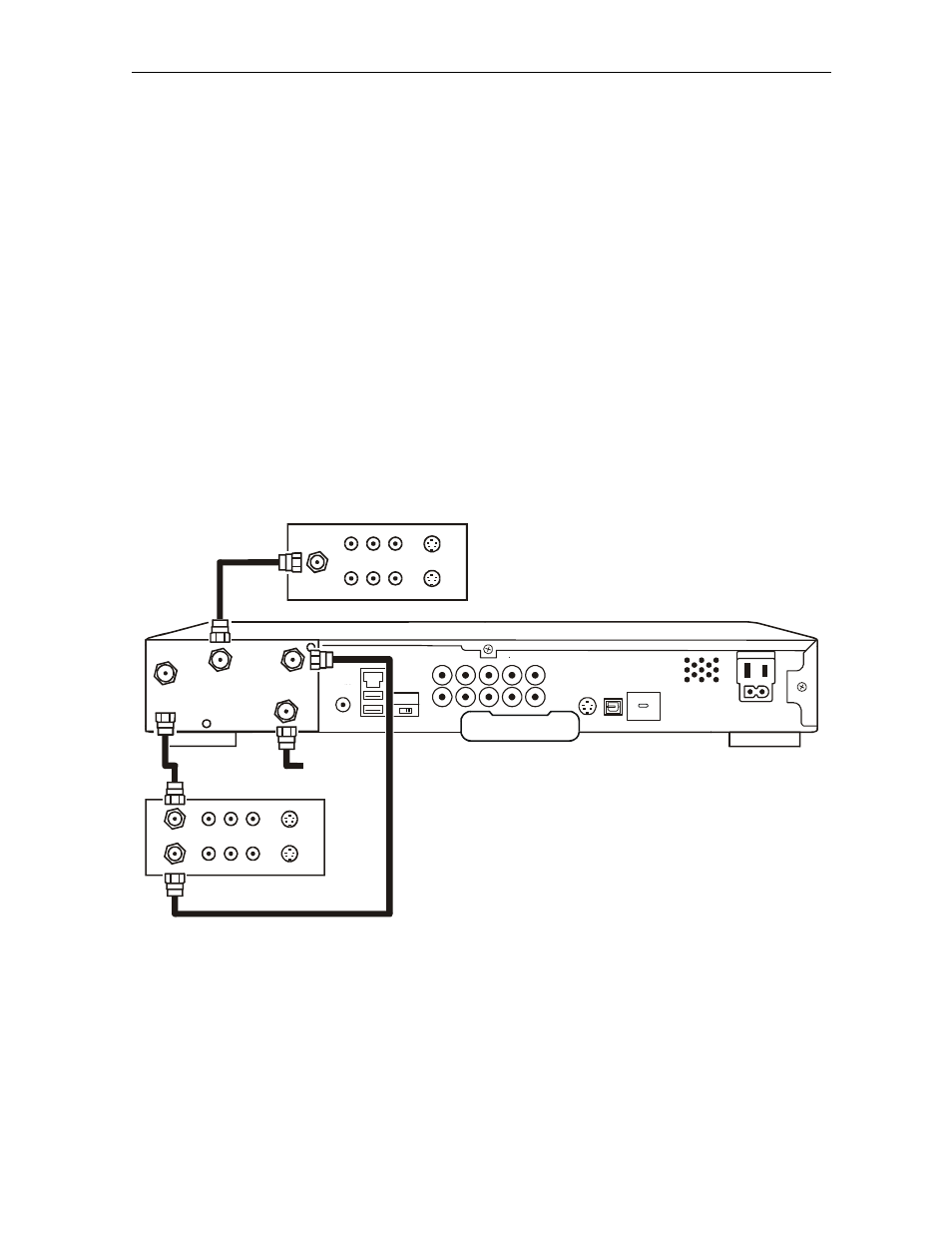
RF Bypass Switch Cabling Diagrams
The RF Bypass switch enables the cable signal to pass directly to a cable-ready TV, bypassing
the DCT5100. The bypass mode is automatically initiated under one of three conditions: when
the DCT5100 loses power, when it is turned off from the front panel, or when the user manually
activates the switch by pressing the A/B key. If the DCT5100 loses power or is turned off, the
subscriber can continue viewing the clear analog channels on the cable system. Activating
bypass mode enables you to tape a tuned channel from the DCT5100 while watching a different
clear channel that is bypassed to the TV.
Proper operation of the RF Bypass feature requires special configuration information from the
control system, and proper user interface settings in the Electronic Program Guide (EPG).
Figure 3-2 illustrates RF cabling to an optional VCR using the RF Bypass switch. When a VCR
is not present, install the supplied jumper cable from the
CONV OUT
to
CONV IN
on the RF Bypass
switch.
Figure 3-2
RF Bypass switch
ETHERNET
HPNA
AUDIO IN
AUDIO
OUT
VIDEO
IR
R
IN
R
L
OUT
S-VIDEO
IEEE 1394
OPTICAL
SPDIF
SPDIF
L
Y
Pb
Pr
TV
Pass Card
SWITCHED
105-125V
60Hz
4A MAX
500W MAX
CONVENIENCE
OUTLET
DCT 5100
CABLE IN
VIDEO IN
AUDIO IN
L
R
CABLE OUT
VIDEO OUT
AUDIO OUT
L
R
SVIDEO IN
SVIDEO OUT
CABLE IN
VIDEO IN
AUDIO IN
L
R
VIDEO OUT
AUDIO OUT
L
R
SVIDEO IN
SVIDEO OUT
TV
VCR (optional)
CONV
OUT
CABLE
IN
CONV
IN
RF
OUT
USB
From
cable outlet
The DCT5100 RF output does not carry stereo for digital channels. All VCR recordings made
using this connection will be in mono for digital channels.