Process input, 1 process input parameters, Process input parameters – Super Systems 3L Series User Manual
Page 23
Series 3L Indicators
23
6. Process Input
Parameters in the input list configure the input to match your sensor. These parameters provide the following
features:-
Input Type and
linearization
Thermocouple (TC) and 3-wire resistance thermometer (RTD) temperature detectors
Linear input (-10 to +80mV) through external shunt or voltage divider, mA assumes a
2.49
Ω external shunt.
See the table in section 6.1.1. for the list of input types available
Display units and
resolution
The change of display units and resolution will all the parameters related to the process
variable
Input filter
First order filter to provide damping of the input signal. This may be necessary to prevent
the effects of excessive process noise on the PV input from causing poor control and
indication. More typically used with linear process inputs.
Fault detection
Sensor break is indicated by an alarm message ‘Sbr’. For thermocouple it detects when
the impedance is greater than pre-defined levels; for RTD when the resistance is less
than 12
Ω.
User calibration
Either by simple offset or by slope and gain. See section 12.2. for further details.
Over/Under range
When the input signal exceeds the input span by more than 5% the PV will flash
indicating under or over range. If the value is too high to fit the number of characters on
the display ‘HHHH’ or ‘LLLL’ will flash. The same indications apply when the display is
not able to show the PV, for example, when the input is greater than 999.9
o
C with one
decimal point.
6.1
Process Input Parameters
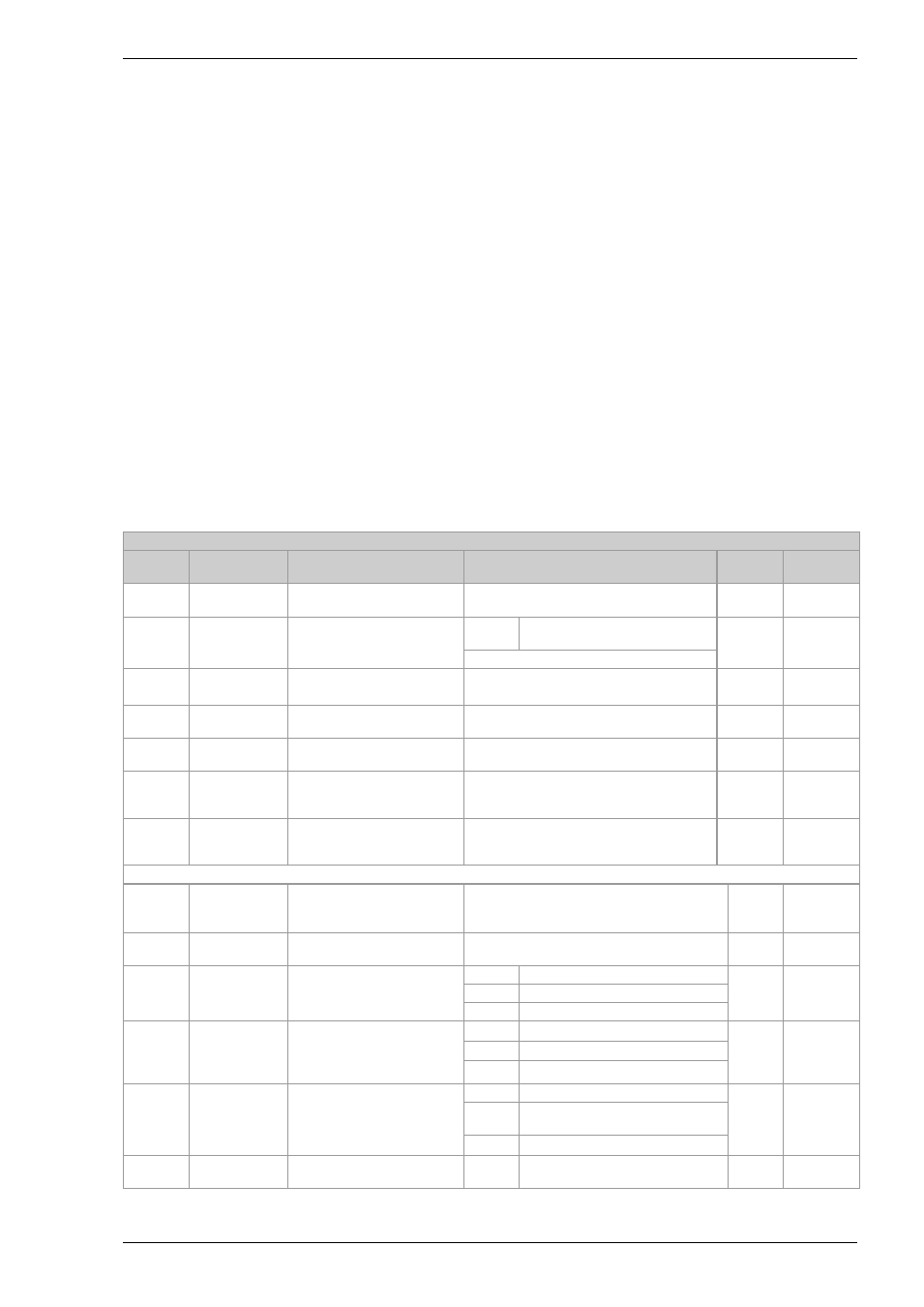
INPUT LIST
I N P U T
Name
Scrolling
Display
Parameter Description
Value
Default
Access
Level
IN.TYP
INPUT TYPE
Selects input linearization
and range
See section 6.1.1. for input types available
Conf
L3 R/O
UNITS
DISPLAY
UNITS
Display units shown on the
instrument
none No units - only for custom
linearisation
o
C
L3
For a full list of units see section 6.1.2.
DEC.P
DISPLAY
POINTS
Decimal point position
nnnnn - No decimal point to n.nnnn - four
decimal points
nnnnn
Conf
L3 R/O
INP.HI
LINEAR
INPUT HIGH
High limit for mV (mA) inputs
(1)
-10.00 to +80.00mV
80.00
Conf
INP.LO
LINEAR
INPUT LOW
Low limit for mV (mA) inputs
(1)
-10.00 to +80.00mV
-10.00 Conf
RNG.HI
RANGE HIGH
LIMIT
Range high limit for
thermocouple RTD and mV
inputs
(1)
From the high limit of the selected input
type to the ‘Low Range Limit’ parameter
minus one display unit.
Conf
L3 R/O
RNG.LO
RANGE LOW
LIMIT
Range low limit for
thermocouple RTD and mV
inputs
(1)
From the low limit of the selected input
type to the ‘High Range Limit’ parameter
minus one display unit.
Conf
L3 R/O
(1) See section 6.1.3 for an example of how to adjust the above four parameters.
PV.OFS
PV OFFSET
A simple offset applied to all
input values.
See section 6.1.3.
Generally one decimal point more than PV
L3
FILT.T
FILTER TIME
Input filter time constant
(first order digital filter)
OFF to 100.0 seconds
1.6
L3
FILT.D
DISPLAY
FILTER
Provides a filter for the
displayed value
Off
No display filter
Off
L3
1
Zero the least significant digit
2
Zero the two least significant digits
CJ.TYP
CJC TYPE
Configuration of the CJC
type
(only shown for
thermocouple inputs)
Auto Automatic
Auto Conf and if
T/C
L3 R/O
0
o
C
Fixed at 0
o
C
50
o
C
Fixed at 50
o
C
SB.TYP
SENSOR
BREAK TYPE
Defines the action which is
applied to the output if the
sensor breaks (open circuit)
oFF
No sensor break will be detected
on
Conf
L3 R/O
on
Open circuit sensor will be
detected
Lat
Latching
SB.DIR
SENSOR
BREAK
Defines the direction in
which the PV will range.
up
Up scale. Output goes to
maximum
up
Conf