7 wire sizes, 8 sensor input (measuring input), 9 outputs – Super Systems 3L Series User Manual
Page 7: 1 output 1 & output 3, 2 aa relay form c (fm approved), 3 transmitter supply, Wire sizes, Sensor input (measuring input), Outputs, Output 1 & output 3
Series 3L Indicators
7
1.7 Wire Sizes
The screw terminals accept wire sizes from 0.5 to 1.5
mm (16 to 22AWG). Hinged covers prevent hands or
metal making accidental contact with live wires. The
rear terminal screws should be tightened to 0.4Nm (3.5
in-lbs).
1.8 Sensor Input (Measuring Input)
• Do not run input wires with power cables
• When shielded cable is used, it should be
grounded at one point only
• Any external components (such as zener barriers)
connected between sensor and input terminals
may cause errors in measurement due to
excessive and/or un-balanced line resistance, or
leakage currents.
• Not isolated from the logic outputs & digital inputs
Thermocouple Input
• Use the correct compensating cable, preferably
shielded.
• It is not recommended to connect two or more
instruments to one thermocouple.
RTD Input
• The resistance of the three wires must be the
same. The line resistance may cause errors if it
exceeds 22
Ω.
Linear mA, or mV Inputs
• For a mA input,
connect the 2.49
Ω burden resistor
supplied between the V+ and V- terminals as
shown. For mV, omit this resistor.
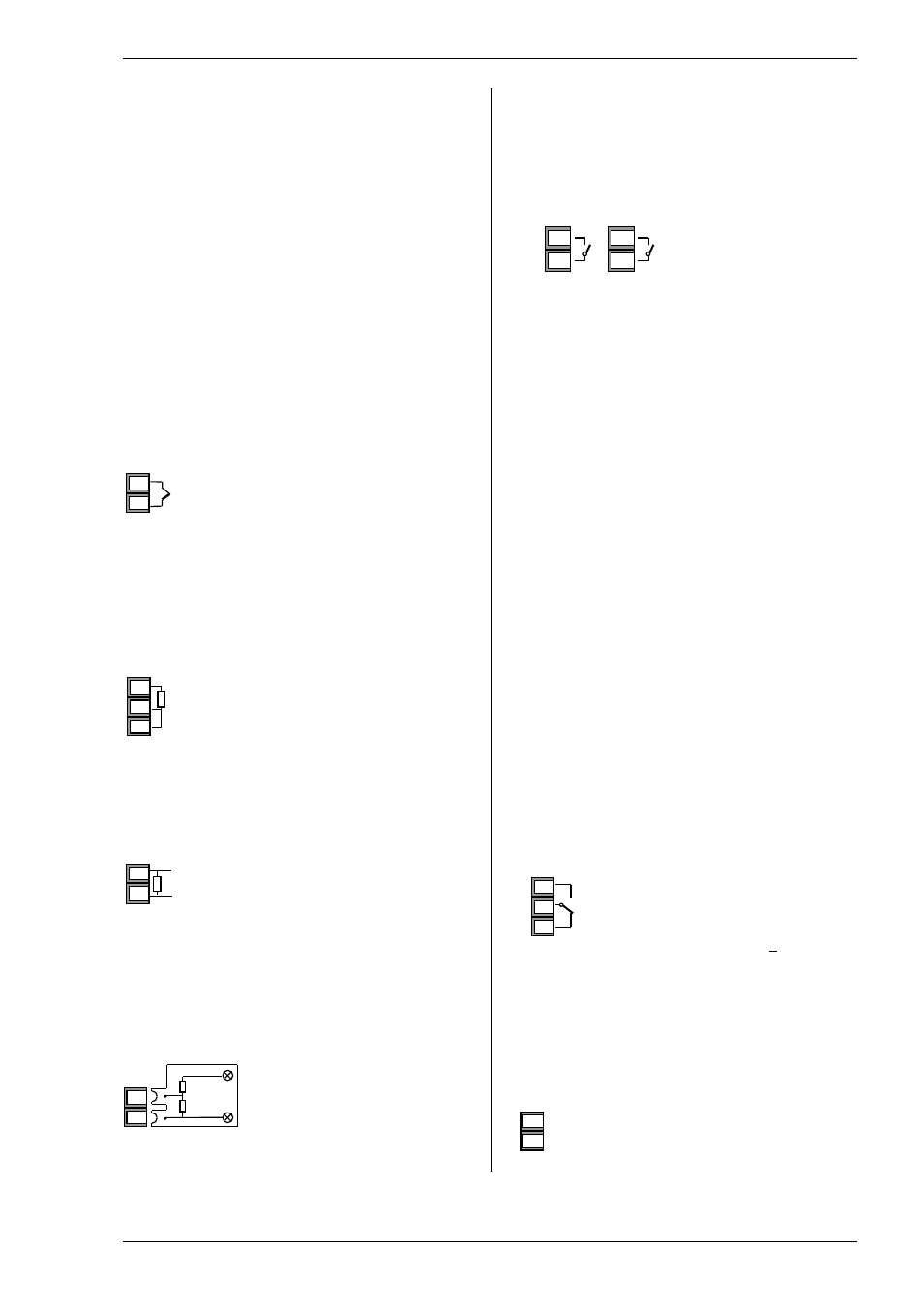
Linear Voltage Inputs
An external potential
divider is required for the
Series 3L
Sensor break alarm does not operate if this adaptor is
fitted.
1.9 Outputs
The indicators are supplied as standard with two
changeover relay outputs as follows:.
1.9.1 Output 1 & Output 3
Relay (Form A)
• Isolated output 300Vac CATII
• Contact rating:: 2A 264Vac resistive
• Output functions: Alarm/Event
* General Notes about Relays and Inductive Loads
High voltage transients may occur when switching
inductive loads such as some contactors or solenoid
valves. Through the internal contacts, these transients
may introduce disturbances which could affect the
performance of the instrument.
For this type of load it is recommended that a ‘snubber’
be connected across the normally open contact of the
relay switching the load. The snubber recommended
consists of a series connected resistor/capacitor
(typically 15nF/100
Ω). A snubber will also prolong the
life of the relay contacts.
A snubber should also be connected across the output
terminal of a triac output to prevent false triggering
under line transient conditions.
WARNING
When the relay contact is open, or it is connected
to a high impedance load, it passes a current
(typically 0.6mA at 110Vac and 1.2mA at 230Vac).
You must ensure that this current will not hold on
low power electrical loads. If the load is of this
type, the snubber should not be connected.
1.9.2 AA Relay Form C (FM Approved)
o
Isolated output 300Vac CATII
o
Software configurable: 0-20mA or 4-
20mA plus 0-5V, 0-10V, 1-5V and 2-
10V.
o
Max load resistance: 500
Ω
o
Calibration accuracy: +(<0.25% of
reading + <50
µA
1.9.3 Transmitter Supply
A fixed 24Vdc supply is available to power an external
transducer
•
Isolated output 300Vac CATII
100K
Ω
806
Ω
+
0-10V
Input
-
V+
V-
+
-
3C
3D
VI
V+
V-
PRT
PRT
Lead compensation
-
+
V+
V-
Positive
Negative
2.49
Ω
-
+
V+
V-
Positive
Negative
OP4
AA
AB
AC
OP1
OP3
1A
1B
3A
3B