Calibration, 1 to check input calibration, 1 precautions – Super Systems 3L Series User Manual
Page 46: 2 to check mv input calibration, 3 to check thermocouple input calibration, To check input calibration, Precautions, To check mv input calibration, To check thermocouple input calibration
Operations Manual
Series 3L
46
12. Calibration
All ranges are calibrated during manufacture to
traceable standards for every input type. When
changing ranges it is not necessary to calibrate the
indicator. Furthermore, the use of a continuous
automatic zero correction of the input ensures that the
calibration of the instrument is optimized during normal
operation.
To comply with statutory procedures such as the
Heat Treatment Specification AMS2750, the
calibration of the instrument can be verified and re-
calibrated if considered necessary in accordance
with the instructions given in this chapter.
For example AMS2750 states:-
"Instructions for calibration and recalibration of ‘field test
instrumentation’ and ‘control monitoring and recording
instrumentation’ as defined by the NADCAP Aerospace
Material Specification for pyrometry AMS2750D clause
3.2.5 (3.2.5.3 and sub clauses) including Instruction for
the application and removal of offsets defined in clause
3.2.4”.
12.1 To Check Input Calibration
The PV Input may be configured as mV, mA,
thermocouple or platinum resistance thermometer.
12.1.1 Precautions
Before checking or starting any calibration procedure
the following precautions should be taken:-
1. When calibrating mV inputs make sure that the
calibrating source output is set to less than
250mV before connecting it to the mV
terminals. If accidentally a large potential is
applied (even for less than 1 second), then at
least one hour should elapse before
commencing the calibration.
2. RTD and CJC calibration must not be carried
out without prior mV calibration.
3. A pre-wired jig built using a spare instrument
sleeve may help to speed up the calibration
procedure especially if a number of
instruments are to be calibrated.
4. Power should be turned on only after the
instrument has been inserted in the sleeve of
the pre-wired circuit. Power should also be
turned off before removing the instrument from
its sleeve.
5. Allow at least 10 minutes for the instrument to
warm up after switch on.
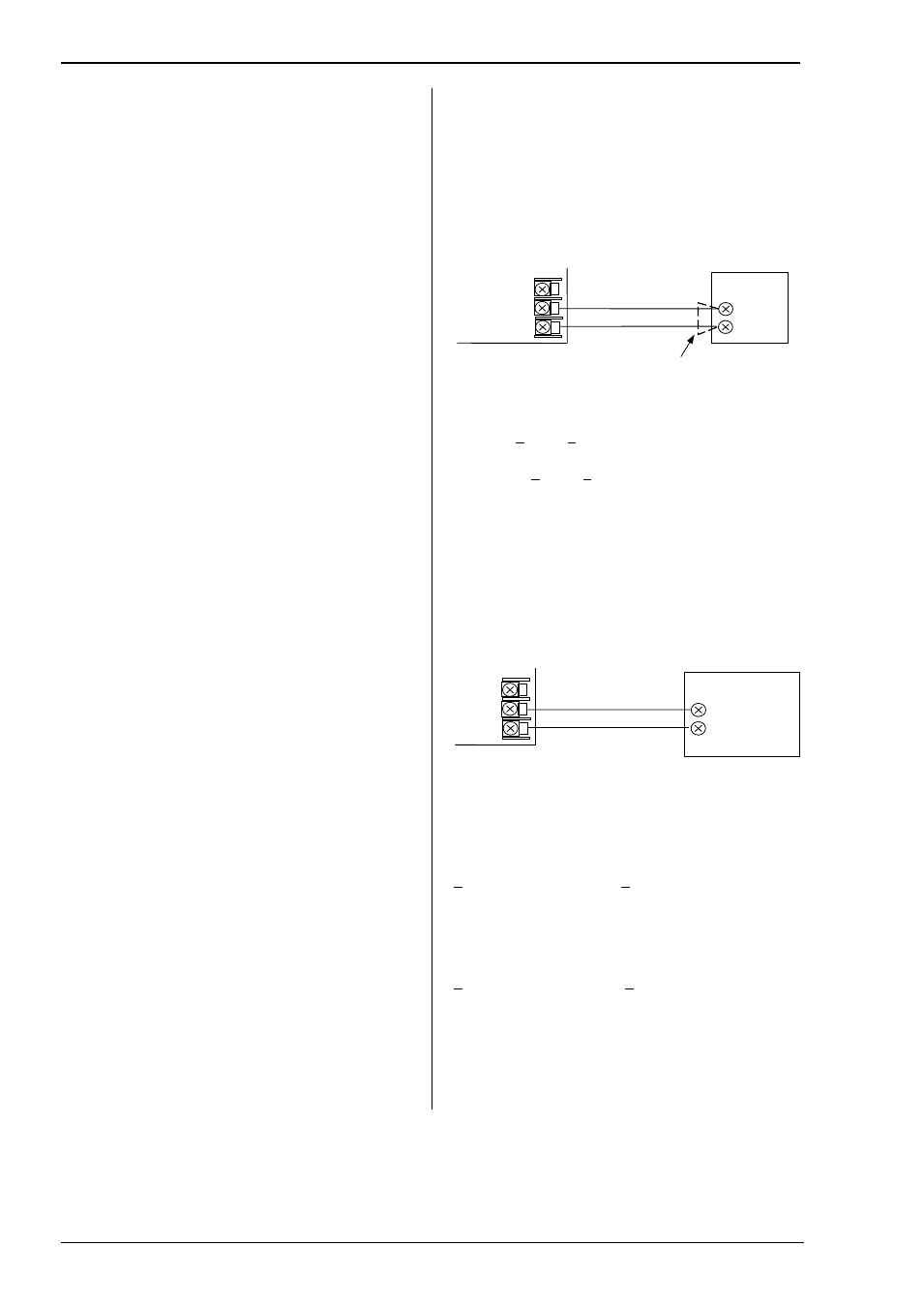
12.1.2 To Check mV Input Calibration
The input may have been configured for a process input
of mV, Volts or mA and scaled in Level 3 as described
in section 5. The example described in section 6.1.4
assumes that the display is set up to read 2.0 for an
input of 4.000mV and 500.0 for an input of 20.000mV.
To check this scaling, connect a milli-volt source,
traceable to national standards, to terminals V+ and V-
using copper cable as shown in the diagram below.
Ensure that no offsets (see sections 6.1.3 and 12.2)
have been set in the indicator.
Set the mV source to 4.000mV. Check the display
reads 2.0 +0.25% + 1LSD (least significant digit).
Set the mV source to 20.000mV. Check the display
reads 500.0 +0.25% + 1LSD.
12.1.3 To Check Thermocouple Input Calibration
Connect a milli-volt source, traceable to national
standards, to terminals V+ and V- as shown in the
diagram below. The mV source must be capable of
simulating the thermocouple cold junction temperature.
It must be connected to the instrument using the correct
type of thermocouple compensating cable for the
thermocouple in use.
Set the mV source to the same thermocouple type as
that configured in the indicator.
Adjust the mV source to the minimum range. For a type
J thermocouple, for example, the minimum range is -
210
O
C. However, if it has been restricted using the
Range Low parameter then set the mV source to this
limit. Check that the reading on the display is within
+0.25% of minimum range + 1LSD.
Adjust the mV source for to the maximum range. For a
type J thermocouple, for example, the maximum range
is 1200
O
C. However, if it has been restricted using the
Range High parameter then set the mV source to this
limit. Check that the reading on the display is within
+0.25% of maximum range + 1LSD.
Intermediate points may be similarly checked if
required.
Copper cable
mV
Source
+
-
Indicator VI
V-
V+
Thermocouple
Compensating cable
Thermocouple
simulator set to
T/C type
+
-
Indicator
VI
V-
V+