4 to check rtd input calibration, 2 offsets, 1 five point offset – Super Systems 3L Series User Manual
Page 47: To check rtd input calibration, Offsets, Five point offset, N 12.2. f
Series 3L Indicators
47
12.1.4 To Check RTD Input Calibration
Connect a decade box with total resistance lower than
1K and resolution to two decimal places in place of the
RTD as indicated on the connection diagram below
before the instrument is powered up. If at any
instant the instrument was powered up without this
connection then at least 10 minutes must elapse from
the time of restoring this connection before RTD
calibration check can take place.
The RTD range of the instrument is -200 to 850
O
C. It
is, however, unlikely that it will be necessary to check
the instrument over this full range.
Set the resistance of the decade box to the minimum
range. For example 0
O
C = 100.00
Ω. Check the
calibration is within +0.25% of 0
O
+ 1LSD.
Set the resistance of the decade box to the maximum
range. For example 200
O
C = 175.86
Ω. Check the
calibration is within +0.25% of 200
O
+ 1LSD.
12.2 Offsets
The process value can be offset to take into account
known errors within the process. The offset can be
applied to any Input Type (mV, V, mA, thermocouple or
RTD).
A single offset can be applied - the procedure is carried
out in the
INPUT list and has been described in section
It is also possible to adjust the low and high points as a
five point offset. This can only be done in Level 3 in the
‘
Cal’ list and is described below.
12.2.1 Five Point Offset
A five point offset may be used to compensate for
transducer or measurement non-linearities. The
diagram shows an example of the type of discontinuity
which might occur in a system.
In this case adjust each point in turn for the VALUE
WHICH THE INDICATOR SHOULD READ. For
example if the value at point 1 should be 1.2345 then
set
Pnt.1 to this value. The following example shows
how to do this.
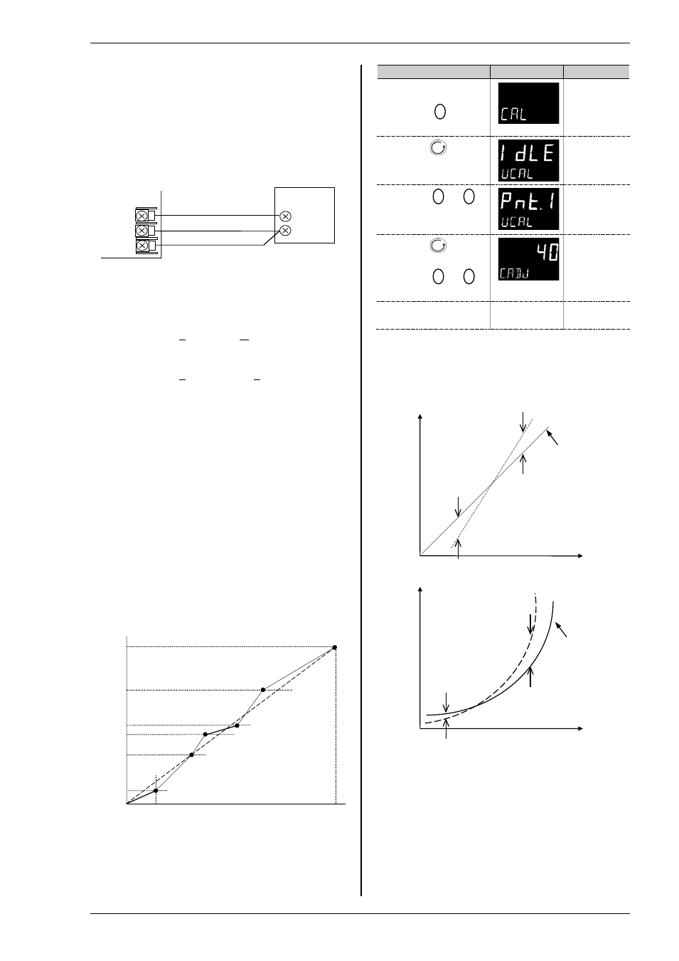
Do This
Display View
Notes
1.
Select Level 3 as
described in Chapter 2.
Then press
to
select ‘CAL’
Scrolling
message
c a l i b r a t i o n
l i s t
2.
Press
to scroll
to ‘u.cal’
Scrolling
message
u s e r
c a l i b r a t i o n
3.
Press
or
to ‘
pnt.1’
To revert to
the original
values,
select
rSet
4.
Press
to scroll
to ‘C.Adj’
5.
Press
or
to the correct value
Note:- this is
not an offset
value
6.
Repeat the above
for points 1 to 5
In some cases it will not be necessary to adjust all 5
points. For example, a low and high adjustment may be
all that is necessary as shown in the following
diagrams.
In this case set
Pnt.1 to the required low point value.
For the high point value you may select any point
Pnt.2 to Pnt.5. The instrument applies a straight line
between the two points.
Note:-
The calibration points must be chosen consecutively –
the five point calibration will not work if a higher point is
inserted between other points.
Electrical
Input
Display
Reading
High offset
(e.g. 6)
Factory
calibration
Low offset
(e.g. 1)
Electrical
Input
Display
Reading
High offset
Factory
calibration
Low offset
Output Hi
Output Lo
Input Hi
Input Lo
Cal Point 5
Cal Point 4
Cal Point 3
Cal Point 2
Cal Point 1
Matched impedance copper
leads
Decade
Box
Indicator
VI
V-
V+