4 digital inputs a and b, 10 indicator power supply, 11 digital communications (optional) – Super Systems 3L Series User Manual
Page 8: Digital inputs a and b, Indicator power supply, Digital communications (optional), Eia 485 connections
Operations Manual
Series 3L
8
1.9.4 Digital Inputs A and B
• Not isolated from the sensor input
• Switching: 12Vdc at 40mA max
• Contact open > 500Ω. Contact closed < 200Ω
• Input functions: Please refer to the list in the quick
codes.
1.10 Indicator Power Supply
1. Before connecting the indicator to the power line,
make sure that the line voltage corresponds to the
description on the identification label.
2. Use copper conductors only.
3. The power supply input is not fuse protected. This
should be provided externally.
4. For 24V, the polarity is not important.
• High voltage supply: 100 to 230Vac, +15%,
48 to 62 Hz
• Recommended external fuse ratings are as
follows:
For 100 - 230Vac, fuse type: T rated 2A
250V.
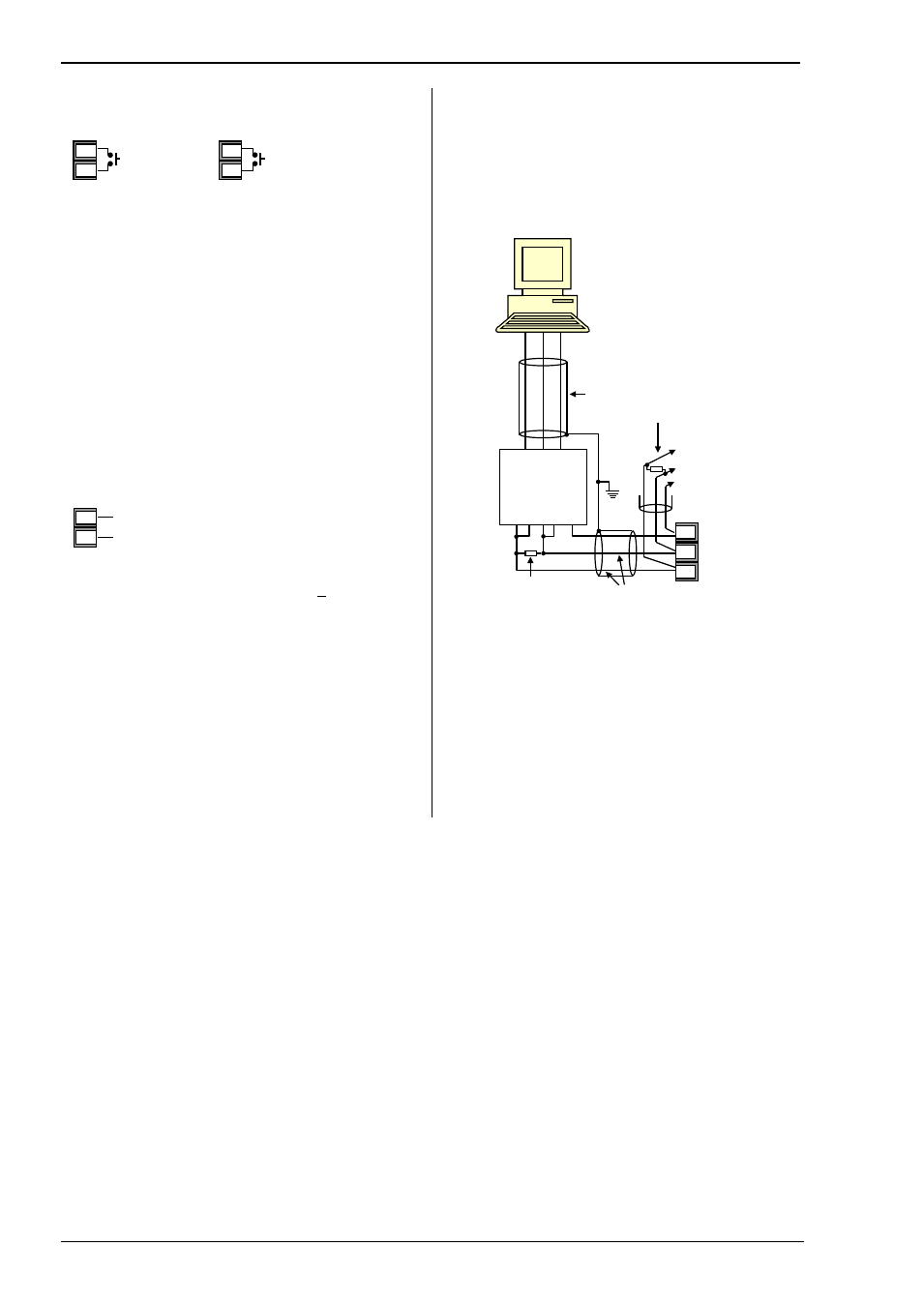
1.11 Digital Communications (Optional)
Digital communications uses the Modbus protocol.
The interface is EIA485 (2-wire).
• Isolated 300Vac CATII.
EIA 485 Connections
Dig In A
LA
C
Dig In B
LB
LC
220
Ω termination
resistor
* EIA232/ EIA485 2-
wire communications
converter eg Type
KD485
Daisy Chain
to further
instruments
Com
220
Ω termination
resistor on last
instrument in the line
Twisted pairs
Tx Rx Com
Rx Tx Com
Screen
RxB/
TxB
RxA/
TxA
*
HD Common
HE Rx
HF Tx
Line
Neutral
L
N