5 parameter modbus addresses, Parameter modbus addresses – Super Systems 3L Series User Manual
Page 43
Series 3L Indicators
43
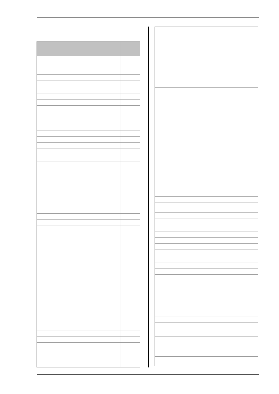
11.5 Parameter Modbus Addresses
Parameter
Mnemonic
Parameter Name
Modbus
Address
(Decimal)
PV.IN
PV (Temperature) Input Value (see
also Modbus address 203 which
allows writes over Modbus to this
variable).
1
RNG.LO
Input Range Low Limit
11
RNG.HI
Input Range High Limit
12
A1.---
Alarm 1 Threshold
13
A2.---
Alarm 2 Threshold
14
Cal offset 4
26
LOC.t
Local Trim – added to the remote
setpoint to compensate for local
temperature variations in a control
zone.
27
A1.HYS
Alarm 1 Hysteresis
47
Cal point 4
66
Cal point 3
67
A2.HYS
Alarm 2 Hysteresis
68
A3.HYS
Alarm 3 Hysteresis
69
A4.HYS
Alarm 4 Hysteresis
71
StAt
Instrument Status. This is a bitmap:
B0 – Alarm 1 Status
B1 – Alarm 2 Status
B2 – Alarm 3 Status
B3 – Alarm 4 Status
B5 – Sensor Break Status
B10 – PV Overrange (by > 5% of
span)
B12 – New Alarm Status
In each case, a setting of 1 signifies
‘Active’, 0 signifies ‘Inactive’.
75
A3.---
Alarm 3 Threshold
81
A4.---
Alarm 4 Threshold
82
Di.IP
Digital Inputs Status. This is a
bitmap:
B0 – Logic input 1A
B1 – Logic input LA
B2 – Logic input LB
B7 – Power has failed since last
alarm acknowledge
A value of 1 signifies the input is
closed, otherwise it is zero. Values
are undefined if options are not
fitted or not configured as inputs.
87
FILT.T
Input Filter Time
101
Home
Home Display.
0 – Standard PV display
4 – PV and Alarm 1 setpoint
6 – PV only
7 – PV and Alarm 1 setpoint read
only
106
-
Instrument version number. Should
be read as a hexadecimal number,
for example a value of 0111 hex is
instrument V1.11
107
-
Static message
108
-
Instrument type code.
122
HIGH
Peak high
126
LOW
Peak low
127
ADDR
Instrument Comms Address
131
PV.OFS
PV Offset
141
C.Adj
Calibration Adjust
146
IM
Instrument mode
0 – Operating mode - all algorithms
and I/O are active
1 – Standby - control outputs are off
2 – Config Mode - all outputs are
inactive
199
COLOR
Colour change
Green –
Red –
Green normal/Red on alarm –
200
MV.IN
Input value in millivolts
202
PV.CM
Comms PV Value. This may be
used to write to the Process
Variable (temperature) parameter
over Modbus when a linearisation
type of ‘Comms’ is selected,
allowing the instrument to control to
externally derived values.
If sensor break is turned on, it is
necessary to write to this variable
once every 5 seconds. Otherwise a
sensor break alarm will be triggered
as a failsafe. If this is not required,
turn sensor break off.
203
204
CJC.IN
CJC Temperature
215
TARE
Tare enable
Off –
On –
Fail -
223
SBR
Sensor Break Status (0 = Off, 1 =
Active)
258
NEW.AL
New Alarm Status (0 = Off, 1 =
Active)
260
Alarm latch status
261
Ac.All
Acknowledge all alarms (1 =
Acknowledge
274
A1.STS
Alarm 1 Status (0 = Off, 1 = Active)
294
A2.STS
Alarm 2 Status (0 = Off, 1 = Active)
295
A3.STS
Alarm 3 Status (0 = Off, 1 = Active)
296
A4.STS
Alarm 4 Status (0 = Off, 1 = Active)
297
Alarm 1 inhibit
298
Alarm 2 inhibit
299
Alarm 3 inhibit
300
Alarm 4 inhibit
301
REC.NO
Recipe to Recall
313
STORE
Recipe to Save
314
Lev2.P
Level 2 Code
515
UNITS
Display Units
0 – Degrees C
1 – Degrees F
2 – Kelvin
3 – None
4 – Percent
516
Lev3.P
Level 3 Code
517
Conf.P
Config Code
518
Cold
If set to 1 instrument will reset to
factory defaults on next reset or
power cycle.
519
DEC.P
Decimal Point Position
0 – XXXX.
1 – XXX.X
2 – XX.XX
525
STBY.T
Standby Type
0 – Absolute Alarm Outputs Active
530