3 input calibration, 1 to calibrate mv range, 2 to calibrate thermocouple ranges – Super Systems 3L Series User Manual
Page 48: Input calibration, To calibrate mv range, To calibrate thermocouple ranges
Operations Manual
Series 3L
48
12.3 Input Calibration
If the calibration is not within the specified accuracy
follow the procedures in this section:
In Series 3L series instruments, inputs which can be
calibrated are:
•
mV Input. This is a linear 80mV range calibrated
at two fixed points. This should always be done
before calibrating either thermocouple or resistance
thermometer inputs. mA range calibration is
included in the mV range.
•
Thermocouple calibration involves calibrating the
temperature offset of the CJC sensor only. Other
aspects of thermocouple calibration are also
included in mV calibration.
•
Resistance Thermometer. This is also carried out
at two fixed points - 150
Ω and 400Ω.
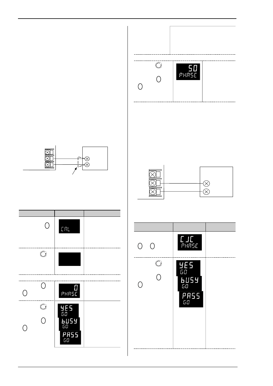
12.3.1 To Calibrate mV Range
Calibration of the mV range is carried out using a 50
milli-volt source, connected as shown in the diagram
below. mA calibration is included in this procedure.
For best results 0mV should be calibrated by
disconnecting the copper wires from the mV source and
short circuiting the input to the indicator
Select Conf Level as described in Chapter 2, s
et the
indicator input to mV range, then:-
Do This
Display View
Additional Notes
1.
From any
display press
as many times as
necessary until the
‘CAL’ page header
is displayed.
Scrolling display
‘
C A L I B R A T I O N
L I S T ’
2.
Press
to
select ‘P H A S E ’
none
p h a s e
Scrolling display
‘
C A L I B R A T I O N
p h a s e ’
3.
Set mV source for 0mV
4.
Press
or
to choose ‘
0’
5.
Press
to
select ‘G O ’
6.
Press
or
to choose
‘
YES’
Scrolling display
‘
C A L I B R A T I O N
s t a r t ’
The indicator
automatically
calibrates to the
injected input mV.
As it calibrates the display will show
busy
then
pass,
assuming a
successful calibration.
If it is not successful then ‘
FAIL
’ will
be displayed. This may be due to
incorrect input mV
7.
Set mV source for 50mV
8.
Press
to
select ‘P H A S E ’
9.
Press
or
to choose ‘
50’
10. Repeat 5 & 6
above
The indicator
calibrates to the
high point in the
same way as the
low point above
12.3.2 To Calibrate Thermocouple Ranges
Thermocouples are calibrated, firstly, by following the
previous procedure for the mV ranges, then calibrating
the CJC.
This can be carried out using an external CJC reference
source such as an ice bath or using a thermocouple mV
source. Replace the copper cable shown in the
diagram below with the appropriate compensating cable
for the thermocouple in use.
Set the mV source to internal compensation for the
thermocouple in use and set the output for 0mV.
Then:-
Do This
Display View
Additional
Notes
1.
From the mV
calibration, press
or
to select
‘
CJC’
2.
Press
to
select ‘GO’
3.
Press
or
to choose ‘
YES’
The indicator
automatically
calibrates to
the CJC input
at 0mV.
As it does this
the display will
show
busy
then
pass
,
assuming a
successful
calibration.
If it is not
successful
then ‘
FAIL
’ will
be displayed.
This may be
due to an
incorrect input
mV
Copper cable
50 mV
Source
+
-
Indicator VI
V-
V+
Thermocouple
Compensating
cable
Thermocouple
simulator set to
T/C type and 0
o
C
+
-
Controller
VI
V-
V+