3 to calibrate rtd ranges, To calibrate rtd ranges – Super Systems 3L Series User Manual
Page 49
Series 3L Indicators
49
12.3.3 To Calibrate RTD Ranges
The two points at which the RTD range is calibrated are
150.00
Ω and 400.00Ω.
Before starting RTD calibration:
•
A decade box with total resistance lower than 1K
must be connected in place of the RTD as
indicated on the connection diagram below before
the instrument is powered up. If at any instant
the instrument was powered up without this
connection then at least 10 minutes must elapse
from the time of restoring this connection before
RTD calibration can take place.
•
The instrument should be powered up for at least
10 minutes.
Before using or verifying RTD calibration:
•
The mV range must be calibrated first.
Do This
Display View
Notes
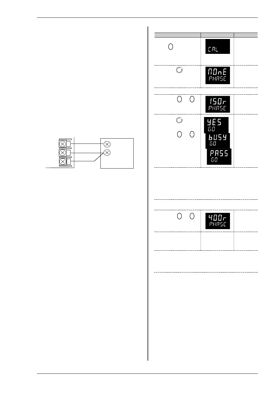
1.
From any display
press
as many
times as necessary until
the ‘C A L ’ page header
is displayed.
Scrolling
display
‘
C A L I B R A
T I O N
L I S T ’
2.
Press
to select
‘P H A S E ’
Scrolling
display
‘
C A L I B R A
T I O N
p h a s e ’
3.
Set the decade box for 150.00
Ω
4.
Press
or
to choose ‘150r’’
5.
Press
to select
‘GO’
6.
Press
or
to choose ‘
YES’
Scrolling
display
‘
C A L I B R A
T I O N
s t a r t ’
The indicator automatically calibrates to the injected
150.00
Ω input.
As it does this the display will show
busy
then
pass
,
assuming a successful calibration.
If it is not successful then ‘
FAIL
’ will be displayed. This
may be due to an incorrect input resistance
7.
Set the decade box for 400.00
Ω
8.
Press
or
to choose ‘400r’’
9.
Repeat 5 and 6
above to calibrate the
high point
The indicator will again automatically calibrate to the
injected 400.00
Ω input.
If it is not successful then ‘
FAIL
’ will be displayed
Matched
impedance
copper leads
Decade Box
Controller
VI
V-
V+