1 input types and ranges, 2 units, Input types and ranges – Super Systems 3L Series User Manual
Page 24: Units, On 6.1.1, On 6.1.1. for, On 6.1.2
Operations Manual
Series 3L
24
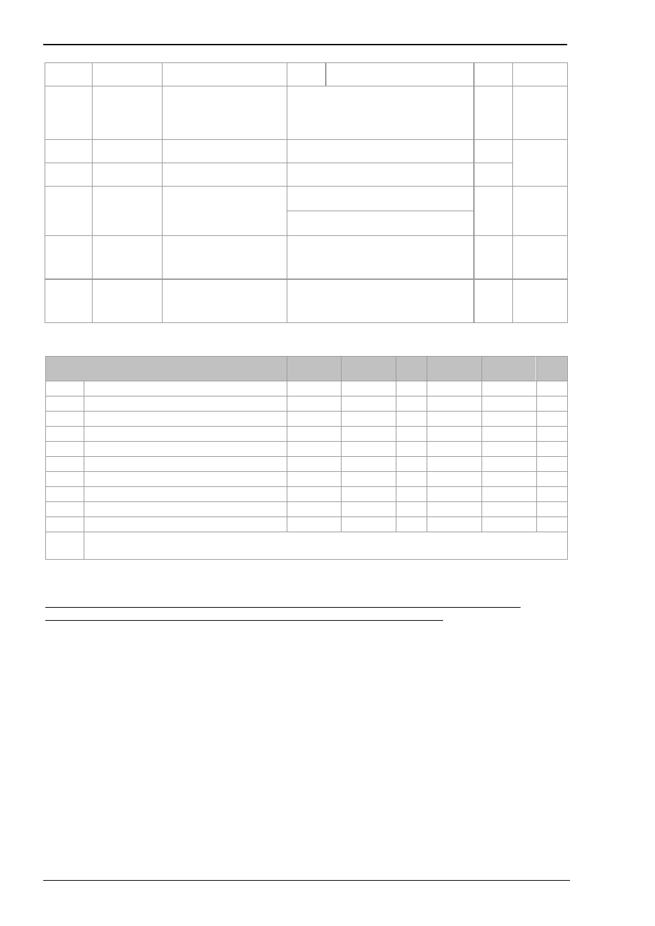
DIRECTION
Dwn
Down scale. Output goes to
minimum
CJC.IN
CJC
TEMPERATUR
E
Temperature measured at
the rear terminal block.
Used in the CJC calculation
(only shown for
thermocouple inputs)
Read only
Conf
L3 R/O
and if T/C
PV.IN
PV INPUT
VALUE
Current measured
temperature
Minimum display to maximum display range
Conf
L3 R/O
MV.IN
MILLIVOLT
INPUT VALUE
Millivolts measured at the
rear PV Input terminals
xx.xx mV - read only
P.RST
PEAK RESET Select ON to reset the HIGH
and LOW peak values. The
display automatically returns
to OFF
OFF
peak
Values
reset
OFF
On
LOW
PEAK LOW
This is the lowest reading
that the indicator has
recorded since switch on or
since it was reset
Read only
L1
HIGH
PEAK HIGH
This is the highest reading
that the indicator has
recorded since switch on or
since it was reset
Read only
L1
6.1.1 Input Types and Ranges
Input Type
Min
Range
Max
Range
Unit
s
Min
Range
Max
Range
Unit
s
J.tc
Thermocouple type J
-210
1200
o
C
-238
2192
o
F
k.tc
Thermocouple type K
-200
1372
o
C
-238
2498
o
F
L.tc
Thermocouple type L
-200
900
o
C
-238
1652
o
F
r.tc
Thermocouple type R
-50
1700
o
C
-58
3124
o
F
b.tc
Thermocouple type B
0
1820
o
C
-32
3308
o
F
n.tc
Thermocouple type N
-200
1300
o
C
-238
2372
o
F
t.tc
Thermocouple type T
-200
400
o
C
-238
752
o
F
S.tc
Thermocouple type S
-50
1768
o
C
-58
3214
o
F
rtd
Pt100 resistance thermometer
-200
850
o
C
-238
1562
o
F
mv
mV or mA linear input
-10.00
80.00
Cms
Value received over digital communications (modbus address 203).
This value must be updated every 5 seconds or the indicator will show sensor break
6.1.2 Units
O
C
o
C
O
F
o
F
O
k
Kelvin
none
No units displayed
Perc
Percentage