Assigning video buses to output connectors, Selecting the video sent to the aux bus, Video input/output settings – Roland VR-6HD Direct Streaming AV Mixer User Manual
Page 17
17
Video Input/Output Settings
Assigning Video Buses to Output Connectors
The VR-6HD features seven types of video buses. You can assign the
signals from each video output connector/port (VIDEO OUT 1–3, USB
STREAM, STREAM/RECORD) and the video shown on this unit’s display to
the desired video bus.
Video output connectors and ports
VIDEO OUT 1–3
VIDEO OUT 1–3 connectors
USB OUT
USB STREAM connector
STREAM/RECORD
DIRECT STREAM port
LCD MONITOR
This unit’s display
Video bus
Explanation
PROGRAM
Final output video.
SUB PROGRAM
Same video as the PROGRAM bus
The SUB PROGRAM bus lets you set whether to
display or hide the PinP & KEY layers and the DSK
layers, separately from the PROGRAM bus.
You can edit the layer settings to output a different
video from that of the PROGRAM bus.
PREVIEW
Preview output video (the video to be output next)
* The fade-in/out effect (p. 32) is not reflected here.
AUX
Video of your choice sent to the AUX bus (p. 17)
This lets you allocate a separate output that is
independent of the final output, such as when you
want a specific input video to be a fixed output.
MULTI-VIEW
The final output video, preview output video and
the videos allocated to the VIDEO SWITCHER [1]–[6]
buttons (multi-view)
MEMO
You can change the left-right videos that are
shown in the upper part of the multi-view.
Set this by pressing the [MENU] button
Ó
“SYSTEM”
Ó
“MULTI-VIEW SETTINGS”
Ó
[MULTI-VIEW
LAYOUT]
Ó
select [LEFT] or [RIGHT].
STILL-VIEW
Still images loaded into the unit (shown as 16
separate sections on the screen)
* For more about the factory settings, refer to “VIDEO OUTPUT ASSIGN” (p. 97).
1 .
[MENU] button
Ó
“VIDEO”
Ó
select “OUTPUT ASSIGN”, and
press the [VALUE] knob.
The OUTPUT ASSIGN screen appears.
2 .
Turn the [VALUE] knob to select the video output connector,
and press the [VALUE] knob.
3 .
Use the [VALUE] knob to edit the value of the setting, and
press the [VALUE] knob.
4 .
Press the [MENU] button to close the menu.
MEMO
Assigning the video buses and audio outputs
You can also assign the desired audio buses (MAIN bus, AUX 1 bus,
AUX 2 bus, MONITOR) for each jack, apart from the video bus (p. 55).
Selecting the Video Sent to the AUX Bus
Here’s how to send the video of your choice to the AUX bus. This lets you
allocate a separate output that is independent of the final output, such as
when you want a specific input video to be a fixed output.
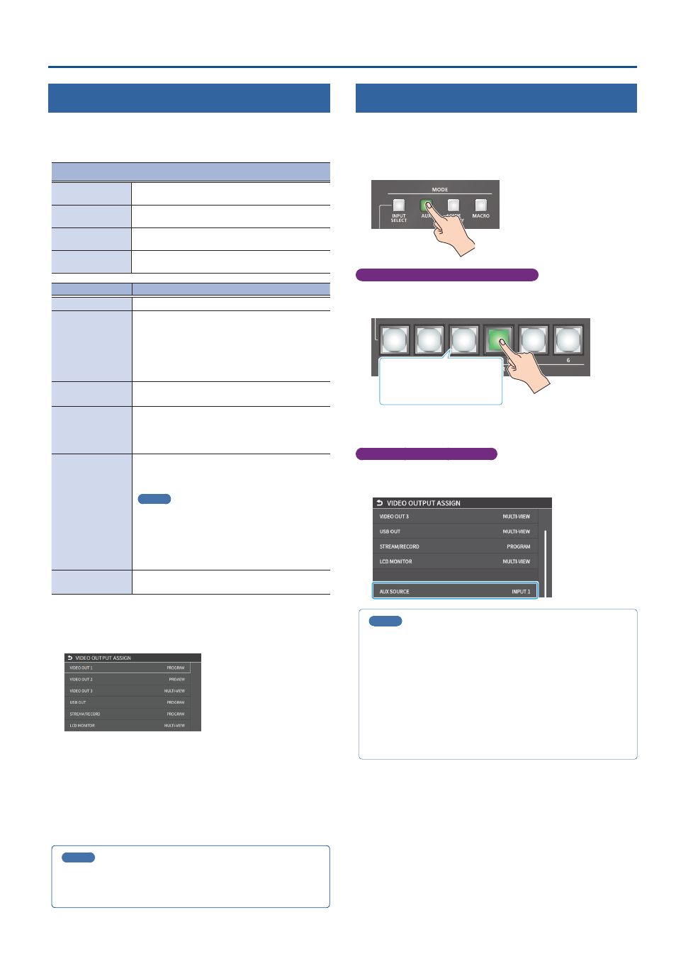
1 .
Press the MODE [AUX] button.
Setting with the VIDEO SWITCHER buttons
2 .
Press the VIDEO SWITCHER [1]–[6] buttons to select the
video signal to send to the AUX bus.
Green: AUX bus video
White: Video input available
Unlit: Video input unavailable
The video is switched for the output connector to which the AUX bus
is assigned.
Configuring on the setup screen
3 .
Touch the screen to select the video signal to send to the
AUX bus.
MEMO
¹
You can adjust how much audio is sent to the AUX bus.
“Sending Audio to the AUX Bus” (p. 55)
¹
Sending the same video as the final output to the AUX bus (AUX
link)
You can use the AUX link function to send the same video as the
final output video to the AUX bus. The video sent to the AUX bus
automatically switches in tandem with the video transitions.
From the [MENU] button
Ó
“SYSTEM”, set the “AUX LINKED PGM”
to “AUTO LINK” or “MANUAL LINK” (p. 139).